Thi section includes procedures for field measurements.
Procedure 2.1 - Making Two Wands Match - Console Matching
Here’s how to make two sensors match each other prior to collecting data. This technique will adjust the match values of one of the sensors. It should be performed with both sensors viewing a cloudless sky.
Note: This technique is only recommended if LAI data is to be collected with two wands attached to one console. There are better matching methods for all other cases. See Multiple-Sensor Operation Revisited.
- Attach the two sensors to be matched to the console, and turn on the control unit.
- Place the sensors side by side so they see the same section of blue, cloudless sky, if at all possible. View the readings in Monitor mode (Monitor Mode Navigation).
- Set match values.
- Go to MENU, select Wand Setup, select the wand to be used for Below readings, and press OK.
- Select Match Values and press OK.
- Select Calculate and press OK. The wand chosen in step “a” will be set to match the other wand. Press OK.
- View values in Monitor Mode to confirm match.
- To reset the original calibration values, select View/Set Values from the Match Values menu (Menu > Wand Setup > Select wand > Match Values). Press LOG to reset, then OK.
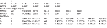
Note that when data are logged, each A or B record contains an indicator (e.g. W1, W2, etc) telling what wand took the data. In the header is a “Contributing Sensors” section that relates the wand indicators to actual serial numbers and match values:
Procedure 2.2 - Opening a New Data File
- With the instrument on, press the START|STOP button.
- Select New File and enter a file name (a maximum of 8 characters or numbers). File names are automatically generated based on the previous entry, incremented by one digit.
- View/Edit remarks, and/or press OK.
- The LAI-2200C is now in Logging Mode. Log A or B readings.
Procedure 2.3 - Import to an Existing Data File
- With the instrument on and a sensor attached, press the START|STOP button.
- Select EXISTING FILE and select a file from the list.
- View/Edit remarks, and/or press OK.
- The LAI-2200C is now in Logging Mode. Log A or B readings.
Hint: It is helpful to sort the list of existing files by modification date, with most recent files near the top of the list. To sort the list that way, press the MENU key when viewing the existing file list, and select Reverse Date. That sort order will remain for subsequent uses until you change it to something else.
Procedure 2.4 - Setting up a Controlled Logging Sequence
The controlled logging sequence is discussed in Controlled Sequence.
- Connect the optical sensor to the control unit.
- Go to MENU > Log Setup > Controlled Sequence and press OK.
- Set the Use field to Yes.
- Set the number of repetitions (from 1 to 41).
- Define the sequence. Press the number "2" button to specify an A reading and the "8" button to specify a B reading (e.g. for the sequence ABBBB, press 28888). The sequence can have up to 20 readings.
- Press OK. The controlled sequence will be used for any new file.
- Create a new file (Procedure 2.2 - Opening a New Data File). To view your position in the sequence, in the logging screen, use the left or right arrow key to change a field to indicate Seq:. This will indicate where you are in the sequence. The wand LEDs indicate which reading is next in the sequence.
The sequence can be interrupted at any time by pressing the A/B|Power button. For example, if the upcoming measurement is specified as an A reading, press the A/B|Power button to change the upcoming reading as a B reading. After logging the data point, the sequence will continue with the next specified measurement.
To deactivate the controlled sequence, set the Use field to No.
Procedure 2.5 - Creating a Match File for Match Method 2
Match methods are discussed in Three Methods for FV2200 Matching.
Set up the A sensor and get it logging. Place the B wand beside it, open a file, and log several A records:
- Press START|STOP button on the control unit, select New File, and name the file "match," or something to identify it as a match file.
- Make sure the B wand is set for A records (the ABOVE LED should be lit).
- Put the sensors together, being as careful as you can that they are both equally leveled and oriented. Press the LOG button several times to capture several A records.
Procedure 2.6 - Logging a 4A or 3A Sequence
Photos and descriptions of these steps are in K Records.
1st A reading - white diffuser, sunlit.
2nd A reading - white diffuser, shaded.
3rd A reading - as wide a view as possible.
4th A reading - normal view cap, normal direction (normal = same as B measurement).
Note that step 3 is optional: If the largest unobstructed view of the sky is no larger that the view with the normal view cap, skip this step, and consider it a 3A sequence.
Procedure 2.7 - Automatic Logging - Wand
This procedure describes how to configure a wand for automatic logging. Discussion is in Automatic Logging (Wand).
- Attach the wand to the console. On the console, go to MENU > Wand Setup > select wand > Auto Log and press OK.
- Select Start Time, and enter the desired start time and day (you can only set the start day of the current month). Press OK.
- Select Stop Time, and enter the desired stop time and day (current month). Press OK.
- Select Frequency and enter a multiple of 5 seconds between 5 and 3600 seconds. Press OK after entering the value.
- Select the On/Off field, highlight On and press OK. The optical sensor can be disconnected from the control unit. If the wand is powered off, it should power up automatically at the specified start time. If these readings are “Above,” be sure that the blue “Above” LED is illuminated. This will ensure that these readings are tagged with an A in the file.
When automatic logging is “On”, the LOG LED light on the wand will blink every 2.5 seconds during the run-up to the logging start time. When it begins logging data, the LOG LED light will blink every second and the wand will beep at the beginning and end of each log.
Note: In wand versions 1.19 and below, automatic logging may not start if you specify a start time that has already passed.
Procedure 2.8 - Automatic Logging - Console
This recipe describes how to configure a console for automatic logging. Discussion is in Automatic logging (Console).
- Go to MENU > Log Setup > Console AutoLog.
- Set the Active field to On. Press the down key to select Period and enter a multiple of 5 seconds between 5 and 3600 seconds. Press OK after entering the value.
When a file is open and autologging is active, the display will show AUTO followed by a countdown to the next log in seconds. All attached sensors (wands and quantum sensors) are logged, and (if enabled) a G0 GPS record.
Procedure 2.9 - Importing A Records - Console
When A readings are collected in a separate file, they need to be imported by the file that holds the B readings before LAI can be computed. This can be done on the control unit (described below) or with the recommended method of using the FV2200 software (Procedure 3.8 - Import A and Adjust A Records - FV2200).
- If it hasn’t been done already, transfer the records from the wand to the console: Go to MENU > Data > Wand Data > Download > select wand. Choose Create new file and name the file.
- Go to MENU > Data > Console Data and select the file that is to receive the imported records. Select the file that has the B readings.
- Select Edit from the menu, then select Import Observations.
- Choose to import A records.
- Press OK and the file will be recomputed using the imported records.
- LAI values will recompute automatically and can be viewed in MENU > Data > Console Data > select file > View Header.
Procedure 2.10 - Excluding Rings from Analysis - Console
The mask determines which rings are used (default = all) to compute LAI. Data from rings that are ignored are still measured and recorded, however, so nothing is lost even if a data file is generated with all rings ignored.
Prior to logging:
- Go to MENU > Log Setup > Masks.
- Select YES for every ring to be used or NO for every ring to be ignored.
- Press OK to keep the settings, EXIT to leave the menu without making changes, or LOG to reset to default settings.
After logging:
- Go to MENU > Data > Console > select data file > Edit > Edit Mask.
- Select YES for every ring to be used or NO for every ring to be ignored.
- Press OK to keep the settings, EXIT to leave the menu without making changes, or LOG to reset to default settings.
Rings can also be excluded in post-processing with the FV2200 software. Follow Procedure 3.5 - Excluding Rings from Analysis - FV2200.
Procedure 2.11 - Interpolating A Records - Console
The Interpolate Transcomp setting will choose the A reading that is closest in time to a given B reading to compute LAI.
- Go to MENU > Log Setup > Transcomp.
- Scroll down to the line below "Determine Above".
- Use the left and right arrow keys to select Interpolate.
- Press OK to keep the settings, EXIT to leave the menu without making changes, or LOG to reset to default settings.
Procedure 2.12 - Getting K Records on an Above Sensor
When a wand is logging A records autonomously, it is possible to also use this wand for getting K record precursors, provided the logging interval is about 30 seconds or more. The goal is to intersperse a 2B or 3B sequence into the file. See Embedded Bs for more explanation.
When it’s time to get another K record, do this:
- Wait for an autolog to occur.
- Push the A/B button to change to B records.
- Remove the view cap, and put the white diffuser in place.
- With the sun on the diffuser, press the LOG button.
- Shade the diffuser, and press the LOG button again.
- (Optional wide sky view). Remove the diffuser. With the sensor shaded, or with a 270° view cap, press LOG again.
- Place the normal view cap back on, and press the A/B button to change back to A records, so that the next autologged reading will be an A.
- Use FV2200 to convert BBBA or BBA sequences to K records (Procedure 3.9 - Generating K records from Sequences).
Procedure 2.13 - Moving Wand Data to the Console
Wand data can be moved to the console and put in a new file or import to an existing file.
- Connect the wand to the console. On the console, go to MENU > Data.
- Select Wand Data and then choose Download.
- Select the optical sensor that has the desired data.
- Select New File to create a new data file or select Add to File to import an existing data file.
- If you choose New File, name the file (up to eight characters) and press OK. If you choose Add to File, select the file from the list and press OK.
It may take several seconds for the file to be transferred and for appended files to be modified. When the file is copied, it remains in the memory of the optical sensor. To delete files from the optical sensor memory, follow Procedure 1.6 - Deleting Records From a Wand.
Procedure 2.14 - Measuring Leaf Transmittance and Reflectance
The theoretical discussion for this procedure is in Required Inputs for the Scattering Model. Leaf transmittance will be labeled LeafTau and leaf reflectance will be LeafRho. This technique was first described in Kobayashi et al., 2013.
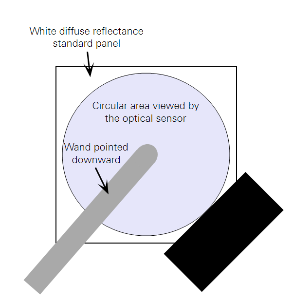
You will need an optical sensor (wand), the drilled cap (lens cap with a small hole in the middle), and a white diffuse reflectance standard panel (about 25 cm by 25 cm). Let Rpanel be the absolute reflectance of the panel. Typical Rpanel for a clean, halon reflectance standard is 0.99. You can use something less reflective, as long as you know its reflectance.
This procedure should be done on a clear day with the sun far enough from the zenith (overhead) so that the sensor will not shade the reflectance panel when mounted above it.
- Attach the drilled cap (with the small hole) to the optical sensor. Attach the optical sensor to the control unit.
- Using a ring stand or other suitable device, mount the optical sensor about 20 cm above the center of the white standard panel, viewing downward. Make sure the sensor or ring stand does not shade the panel.
- Determine the size of the optical sensor’s view by increasingly shading one corner of the white standard panel until the Ring #1 reading begins to change (Figure H‑1). This indicates how far the view extends from the center of the panel. Doing this shading on three corners instead of just one will account for any sensor tilt. Adjust the sensor’s height until its view includes as much of the panel as possible without getting closer than a few centimeters from the panel's edge. All subsequent measurements should be with the sensor locked in this position.
- Hold a leaf against the optical sensor lens cap so that the hole is completely covered by the leaf. Note the Ring #1 reading; we will refer to this value as T.
- Remove the leaf, and note the Ring #1 reading again. This is Tref.
- LeafTau = T / Tref
- Cover the reflectance standard with the type of leaves being measured. Overlap them so that all parts of the panel visible to the sensor are covered. Note the Ring #1 reading; we will refer to this value as R.
- Remove the leaves and any debris and note the Ring #1 reading again. This is Rref.
- LeafRho = R / Rref / Rpanel