Maintenance
In this section we describe maintenance procedures.
Changing the fluorescent tube
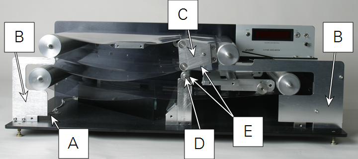
- Grasp the tube near each end by the edges of the upper transparent belt. Twist the tube 1/4 revolution to loosen it in the connectors.
- Remove the rear tube connector by loosening the two recessed mounting screws.
- Draw the tube out through the hole in the instrument rear plate.
- Install the replacement tube as described in Fluorescent tube installation.
Watch a video of this procedure at
licor.com/support/LI-3100C/videos.html
Changing the transparent belts
The following steps are used to remove the transparent belts. An alternative technique is outlined in Alternative belt removal technique.
Watch a video of this procedure at
licor.com/support/LI-3100C/videos.html
- Disconnect the power.
- Remove the rear housing (Rear housing removal).
- Loosen the transparent belts (Transparent belt tension adjustment).
- Remove the fluorescent tube (Changing the fluorescent tube).
- Separate the fluorescent tube power cord connector located near the instrument front plate and under the belt drive pulleys.
- This connector may remain mated if the front plate can rest near the instrument without straining the cord.

- Remove the hexagonal socket screws (7 total) which are directly contacting the instrument plate.
- Other similar screws are visible on the front of the instrument which fasten the pulley support brackets. Do not loosen those screws.
- Remove the front plate slowly, keeping it parallel to prevent binding on the shafts.
- Be certain that all pulleys and idlers remain in place, resting on the support brackets. This is accomplished by repeatedly pressing the pulleys and idlers back into their rear plate bearings.
- Caution: Do not allow the upper belt rocking idler or the lower belt idler to drop onto the mirror located directly beneath these components.
- Draw the upper belt rocking idler and the lower idler outward to remove them.
- Slide the belts outward to remove them.

Caution: Do not exert excessive upward pressure on the drive pulleys as the belts are removed. This will bend the gear shaft which extends through the rear plate bearing
Alternative belt removal technique
Follow steps in Changing the transparent belts and then proceed with the following two steps.
- After the upper belt rocking idler and lower belt idler are removed, then the upper and lower pulleys near the sample tray can be removed (do not remove the drive pulleys).
- Grasp each pulley near each end when they are being removed because they are heavy. Dropping one end may cause severe damage.
- After the belts are placed over the drive pulleys, slide the upper and lower pulleys through the belts and insert the pulley shaft into the rear plate bearing.
- Be sure that the peripheral end groove is toward the front and that it rests in the pulley support bracket.
Replacing the transparent belts
- Slide the lower belt onto the pulleys.
- This requires repeated manipulation at the support brackets because these brackets partially obstruct installation. Then slide the upper belt onto the upper pulleys.
- Replace the lower belt idler.
- Be certain that the peripheral end groove is toward the front and rests on the idler support bracket.
- Replace the upper belt rocking idler.
- Be certain that the notch on the idler end plate rests on the rocking idler support post.
- Connect the fluorescent tube power connector if it was separated when the belts were removed.
- Replace the front plate.
- This requires repeated manipulation at the pulley and idler shafts to insure proper alignment into the front plate bearings.
- Replace all front plate screws.
- Install the fluorescent tube.
- Tighten the transparent belts.
Cleaning the transparent belts
Clean the belts with water and a cloth or absorbent paper. A detergent may be used for persistent contamination but do not allow detergent to fall on the mirrors. Any scrubbing of the mirrors to remove detergent spots may damage the mirror surface. Access to the lower belt is facilitated by momentarily activating the "ON/OFF" switch to rotate the belt so that you can clean the portion of the belt that is near the sample tray. The inner surfaces are cleaned by reaching into the access ports in the front plate. Loosen the belts to facilitate cleaning the pulley surfaces.
Cleaning the mirror or camera lens
If the mirror or the camera lens have to be cleaned, use the "blow brush" provided with the instrument. If persistent dirt remains on the mirror, use water and a soft absorbent paper such as lens paper.
Cleaning the interior of the camera
Cleaning within the camera housing is discouraged unless there is evidence of debris on the scanner (spurious counts). Removing the lens requires two retaining set screws to be removed first. Do not remove the three screws holding the lens base to the square plate. Loosen the screws on the outer camera pressure plate and lift the camera from the rails to more easily inspect the interior. The camera remains connected so do not apply tension to the connection.
The rectangular sensitive device (reticon) is visible at the interior rear of the camera housing. Any speck of dirt on this sensor will cause spurious counting. Use the "blow brush" provided to remove dust. Do not use a moist cloth to clean within the camera housing, as the adhesive dust retaining tape surrounding the reticon and printed circuit board can be damaged.
Cleaning the motor and belt drive system
The motor and belt drive system requires no routine service or lubrication. If excessive debris becomes embedded into the belt, it can be removed with a small stiff brush.
