Operation
Instrument activation
After reading and performing the procedures in Preparations, the following steps should be taken to activate the instrument:
- Connect the supplied power cord to the power input connector at the rear of the instrument. A grounded three prong wall connector is required for electrical service.
- Move the "ON/OFF" switch to "ON".
- Press the "Lamp Start" button (Figure 2‑2) firmly and release after holding for approximately 2 seconds. If the fluorescent tube does not illuminate, repeat the procedure.
- Press the Zero button to clear the display (Figure 2‑2).
Display response
The display will rapidly accumulate numbers when the "ON/OFF" switch is placed in the "ON" position. This accumulation will continue until the fluorescent tube is activated. If numbers continue to accumulate, refer to Troubleshooting for possible remedies.
Data accumulation may continue to occur if the fluorescent tube output is not sufficient, such as initial starting in extremely cold conditions. Excessively low line voltage is also a cause for continued rapid spurious counting.
Belt tension and tracking adjustment
Belt tracking is adjusted by moving the sliding pulley bearing blocks (Figure 2‑2). The belts likely will not maintain alignment without some adjustment. If a belt progresses toward one end of a pulley, then tighten that side of the belt. Fine adjustments are performed by twisting the block adjustment screw to push the sliding bearing block. The knurled knobs located on the pulley bearing blocks must be loosened to allow block movement.
Calibration
General guidelines on the need to calibrate follow.
- After installing a new lamp (let it run for several hours first).
- After replacing extremely worn or cloudy belts.
- When a large change in ambient operating temperature occurs.
- As a result of obvious misadjustment.
Caution: Improper adjustment can seriously decrease the accuracy of finely detailed samples.
Some history
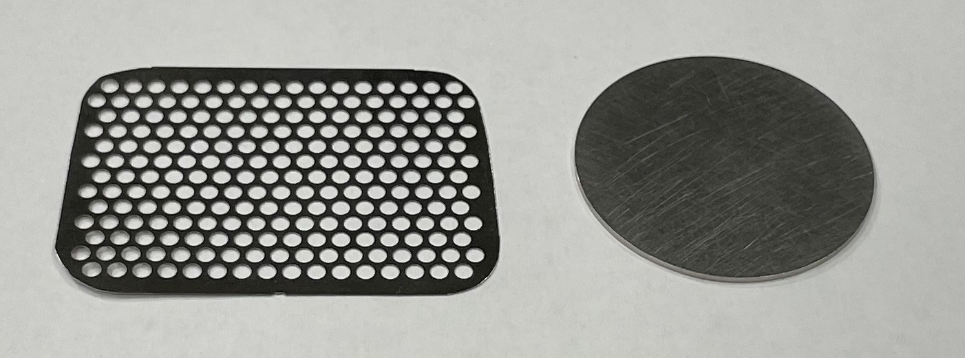
Two calibration discs were included with LI-3100 Area Meters so that users could make minor adjustments of area readout, using the CAL screw on the instrument front panel. The smaller disc was used with the high resolution option, as the larger disc would not fit between the 7.5 cm sample guides used for 0.1 mm2 resolution. The calibration method involved repeatedly measuring the appropriate disc until the average error was less than 0.5 percent for high resolution, or 1 percent for low resolution.
Due to the optical characteristics of the lamp and lens, the discs read higher in the center of the measurement zone than nearer the sample guides, when the LI-3100 was configured for low resolution (1 mm2). However, samples that have a very high ratio of edge to area (i.e., conifer needles, small irregular leaves, roots, etc.) exhibited the opposite effect. In addition, incorrect calibration resulted in larger errors with these samples.
As a result, large changes could be made to the calibration adjustment with little effect on the resulting readout. A large adjustment that makes the average reading appear closer to the area of the round disc could now increase the errors in samples with a high ratio of edge to area.
To address this issue, LI-COR is providing a new 10 cm2 calibration plate (part number 9931-021) with a higher edge to area ratio. The user will find that the calibration adjustment is very sensitive to small changes with this new calibration standard. This “edge-intensive” standard is run through the area meter in a number of positions along the measurement width, after which the round calibration discs (part number 6512-095) are run through in a similar fashion; the round discs should still produce results within the basic accuracy specifications. Thus, the user can view the response of the instrument to the different extremes of sample geometry, and is assured of a better calibration. In addition, for exacting measurements, the user can see which area of the measurement zone yields the highest precision and accuracy.
Calibration procedure
- Start the lamp and allow it to warm up for 5 minutes or more.
- Make sure that the camera position and lens settings match the marks indicated for 0.1 mm2 resolution (see Changing measurement resolution). If transparent belt flaws, or debris on the belt is causing spurious counts on the display, you may need to clean or replace the belt, as necessary.
- Run the edge-intensive standard (part number 9931-021) through the area meter at least 10 times, and average the readings.
- Repeat over all of the areas of the sample width area. For example, use 5 zones from front to back, and repeat to total 10 readings. If the error exceeds 2%, carefully turn the CAL screw a small amount, clockwise to increase, or counterclockwise to decrease. Avoid changing the adjustment too much. It is better to perform several trials, as normal sampling statistics will cause each trial to vary slightly.
- As a confirmation, perform the same 10 measurements with the 10 cm2 round calibration disc (part number 6512-095).
- The errors should remain within the specified limits. It is not necessary to turn the CAL screw until the errors are zero; turning the screw more than a few degrees can actually increase errors in measurement accuracy.
Pressing roller adjustment
Curled leaves are effectively flattened and held rigidly between the transparent belts for more accurate measurements by use of the adjustable pressing roller. This is nearly essential for small grasses, legumes and aquatic plants.
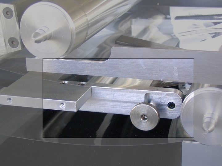
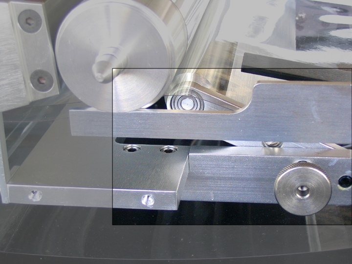
In Figure 3‑2, the front panel is removed to show mechanical details. The retracted position is for use with thick leaves. The fully raised position for use with the thinnest leaf types is shown in Figure 3‑3.
To raise the pressing roller, the lower belt tension must be released to prevent stretching. To do this, simply loosen the knurled knobs on both sides of the sliding bearing blocks for the lower belt. Then loosen the knurled knobs on both sides of the pressing roller and raise to the desired position. After tightening the pressing roller, refer to Transparent belt tension adjustment to adjust the lower belt to its proper tension and alignment.