
Mounting options and considerations
This section describes how to install the LI-550F and LI-550P and it covers considerations for deployment.
Orientation
The LI-550 has a north arrow indicator N on one of the upper arms. Airflow passing directly into the N will return zero degrees for wind direction regardless of the actual orientation of the sensor. Adjustments of wind direction for orientation other than pointing to true north can be done in post processing of data.
We do not recommend mounting the instrument in an upside-down position.
Mounting the LI-550F
The LI-550F can be mounted directly to a user-supplied platform or with the 550FM mounting adapter.
User-supplied mount
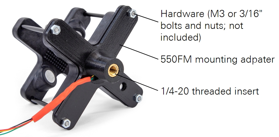
The LI-550F features a flat base with four mounting points for connecting to a user-supplied mounting platform using four M3 or 3/16" bolts. The mounting platform should be flat with a 5-mm hole in the center for the connecting wires and 5.5-mm hole positioned at the Gore-Tex® vent to allow for water vapor and air pressure exchange.

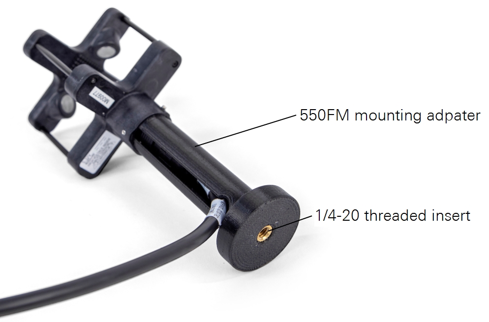
550FM mounting adapter
The 550FM is an optional mounting adapter for attaching the LI-550F to a custom platform. It features a brass ¼-20 threaded insert that is compatible with most camera tripods.
Note: Do not overtighten the mounting hardware. Doing so can damage the glass-filled Nylon anemometer body.

Mounting the LI-550P
The LI-550P can be mounted directly to pipe or with the 550PM mounting adapter.
Pipe mount
The LI-550P mounts to a ½ inch schedule 10 pipe (DN 15) or 22 mm carbon fiber tube. The pipe must have an inside diameter >17.1 mm to allow space for the cable. Set screws are tightened with a 0.05 inch hex key.
Before putting the LI-550P on the pipe, route the cable through the pipe. Then connect the cable to the base connector. Place the LI-550P over the pipe and tighten the set screws. For a detailed description of the internal wiring of the connector and cable see Connecting the power and data cable.

550PM mounting adapter
The 550PM is an optional mounting adapter for attaching the LI-550P to a custom platform. It features a brass ¼-20 threaded insert that is compatible with most camera tripods.

Deployment considerations
If you intend to use data from the compass or accelerometers, either with a single anemometer or to compare with other anemometers, these components should be calibrated in the environment where the device will be deployed.
Note: The magnetic compass is suitable for stationary applications, where data can be averaged over a long time period. It is, however, not suitable for drone application or other applications where the anemometer will be moved.
Compass
A magnetic compass inside the LI-550 measures magnetic north. Since the reading of the compass is highly dependent on the magnetic environment around it, the compass is not calibrated during manufacturing. Instead, you should calibrate the compass in the environment where it will be used, especially if you want to combine data from multiple TriSonica sensors. Compass calibration can be initiated in the menu interface (see Calibration) or command-line interface (see compasscalibrate). See Compass calibration for full details. The raw magnetometer outputs are also available.
Tilt and level
An accelerometer inside the LI-550 measures offsets from level. Because the mounting of the LI-550 affects the tilt, offsets are not set during manufacturing. Persistent offsets in the data could indicate that the calibration needs to be adjusted. Calibration can be initiated in the menu interface (see Calibration) or command-line interface (see levelcalibrate). See Level calibration for more details. The raw accelerometer outputs are also available.
Environmental considerations
The LI-550 is designed for outdoor use1, but some limitations apply. Protect the instrument from sustained rainfall and persistent high humidity (condensing conditions). If the device will sit outdoors unused for long periods, you can cover it to reduce the accumulation of dust, pollen, and other contaminants.
Humidity
The humidity sensor is located inside the LI-550 body. It measures water vapor that passes through the membrane (white Gore-Tex® dot). This causes a delay in the humidity reading when the humidity changes. This delay can be up to an hour for very large humidity changes, such as moving the unit from a 90% RH environment to a 30% RH environment. Normal environmental humidity changes that happen more slowly experience a shorter latency.
Humidity is determined by calculating the dew point inside the anemometer, assuming that the dew point is the same inside and out. The average of the ultrasonic temperature is used to calculate humidity from the dew point.
When an LI-550 is removed from a warm 90% humidity environment to a cooler 30% environment, the rapid change may cause condensation inside the unit, leading to a reported humidity greater than 100%. The reading will persist until the condensation has evaporated and equilibrated through the vent.
Pressure
The absolute pressure sensor is located inside the LI-550. The Gore-Tex® membrane ensures that air pressure inside the device is the same as ambient. A slight delay is noticed with rapid pressure changes.
Ice and snow
The small size and light weight that are the hallmark of the LI-550 leave no space for on-board heaters. If ice or snow accumulate within the LI-550, the acoustic pathways between transducers can be blocked. Although the dark coloring of the LI-550 facilitates natural solar removal of ice and snow, the LI-550 may not be the best choice of sensor for sustained use in wintery weather.
Not submersible
A VE9 series Gore-Tex® vent on the base of the LI-550 allows the internal humidity and air pressure sensors to measure ambient humidity and pressure. The internal mount vent protects the delicate electronics inside from water incursion.
Contact LI-COR if you have questions about the suitability of the LI-550 for your application.
Interference considerations
Be aware of these potential sources of interference as you plan your project.
Other sonic anemometers
If using more than one anemometer, maintain at least one meter separation distance between the two devices to prevent ultrasonic interference. Two anemometers that are close to each other may appear to work fine, but over time, the two clocks will come into phase with each other, leading to spikes in the measurements. Avoid the situation by maintaining at least one meter of separation.
Compact fluorescent lamps
Some compact florescent lamps (CFL) make ultrasonic noise that can interfere with the operation of a LI-550. Erroneous readings may result if the LI-550 is operated near compact florescent lamps. Turn off the CFL or move the sensor away from the CFL to reduce interference.
Wind tunnels and ultrasonic frequency
Ultrasonic anemometers operate by generating ultrasonic pulses and measuring the time of flight of those sound pulses between transducers. The time-of-flight measurements can be disturbed by external noise sources in or near the same frequency band used by the ultrasonic anemometer’s transducers. The LI-550 operates in the 60 KHz ultrasonic frequency range.
We have found that some wind tunnels generate ultrasonic noise that can cause erroneous readings. This is not an indication of failure of the anemometer but is a result of using the anemometer in an ultrasonically noisy environment.
Electro-mechanical motors and magnetic sensors
Electro-mechanical motors generate magnetic fields; the effect of the field on a magnetic sensor varies by distance of the sensor to the motor and by the speed (and variations of speed) at which the motor is operated. The magnetic sensor aboard the LI-550 will be affected by the field generated by ferrous materials and motors nearby. The LI-550 should be placed in a position outside the effects of these fields. We recommend that you consider the effects of magnetic fields arising from your unique configuration in both your hardware and software design.