Connecting to the anemometer
This section describes how to connect the LI-560 and what to expect after connecting.
Serial communication settings
The LI-560 starts generating data about one second after power up, and outputs data continuously when in sampling mode. With the LI-560 connected to a computer by the USB adapter or similar device that supplies power to the LI-560 and allows data pass-through, the serial data stream from the LI-560 can be viewed with the TriSonica application or a terminal emulator.
Connecting with the TriSonica application
Note: This software application is not suitable for data logging functions.
To connect using the TriSonica application:
- Connect the data and power cables and power on the anemometer.
- See Support: LI-560 TriSonica® Sphere Ultrasonic Anemometer.
- Launch the TriSonica application.
- Download from licor.com/support/LI-550/software.html.
- Select the serial port that is used for the USB-to-serial adapter.
- All active ports will be presented in the drop-down list (you can guess which one or find it in your computer's Device Manager). In the example, it is COM3. The software will attempt to connect immediately after selecting the port.
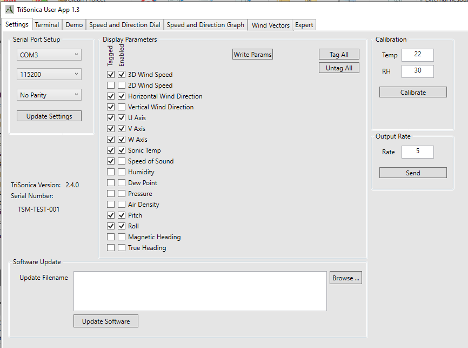
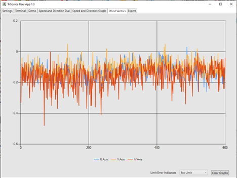
- When connected, you'll see the data stream into the Terminal tab. If display parameters have been set, you can view plots under the other tabs as well: Demo, Speed and Direction Dial, Speed and Direction Graphs, Speed and Direction Graphs, and Wind Vectors.
Connection error or no data? See Support: LI-560 TriSonica® Sphere Ultrasonic Anemometer for help connecting.
Connecting with a terminal emulator
- Connect the data and power cables and power on the anemometer.
- See Connecting the power and data cable.
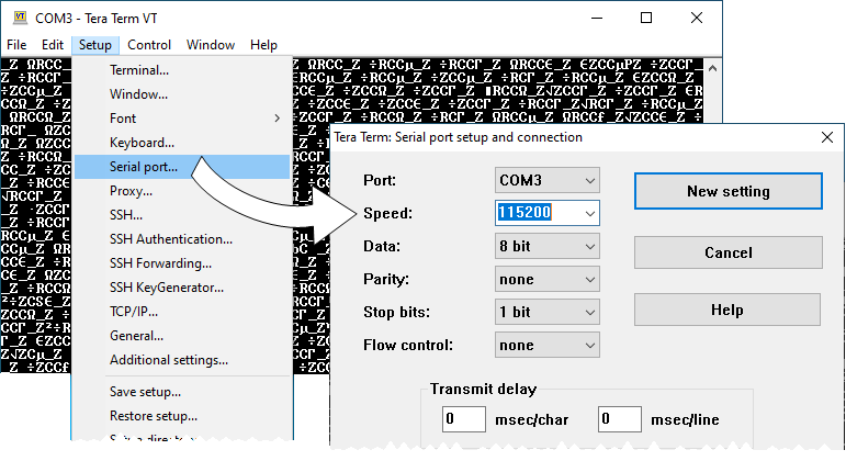
- In Tera Term, start a New connection, select Serial as the connection type, select the Port used by the USB-to-serial adapter, and click OK.
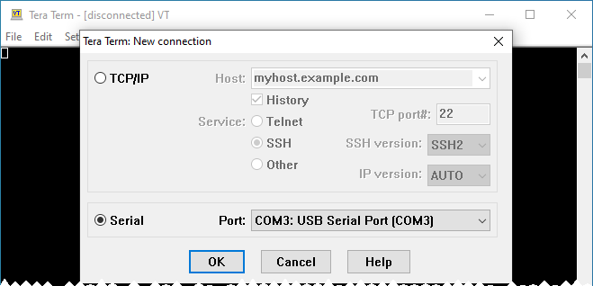
- If the default baud rate of the terminal is incorrect, data will appear as non alpha-numeric characters. To resolve the issue, change the serial port baud rate to 115200 under Setup > Serial port.
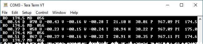
- Data will stream into the Terminal interface.
Connection error, no data, or nonsense data? See Connection issues, no serial data, or the connection fails for help connecting.
Connecting to the LI-570 Data Logger
When the LI-560 is connected to the LI-570 Data Logger, you can configure it through the data logger. In this case, communication is mediated by the logger. Some minor differences may be apparent. See the LI-570 instructions for details.
Configuration options
After connecting with either the TriSonica application or a terminal program, you can configure the anemometer in three ways:
TriSonica Application
In the TriSonica application Settings tab, some configuration options are available, and are selected by checking the appropriate box (see Connecting with the TriSonica application).
Menu interface
In a terminal program or the TriSonica application Terminal tab, press ESC to view the menu (see Support: LI-560 TriSonica® Sphere Ultrasonic Anemometer).
- Press X to discard changes and return to sampling mode.
- Press 0 (zero) to store changes and return to sampling mode.
Command-line interface
In a terminal program or the TriSonica application Terminal tab, press Ctrl + C to enter the command-line interface (see Configuring with the command-line interface).
- Type help to view the command-line help menu.
- Type exit to return to sampling mode.
Serial data format
The LI-560 outputs data in an ASCII character string ending with carriage return and line feed characters. Each line is a single record of all the measured parameters contained in a single sample.
Note: Although you can configure which measurements appear in the data string, the order in which the measurement data appears is not customizable.
The parameters on an output line are separated by two spaces, or by a single space and a negative sign. You can use optional data tags to indicate the measurement associated with the value; the tags can be turned on or off for each individual type measurement. For more about tags, see Basic mode commands.
Parameters
The variables measured by the LI-560, default units, and default tags are listed in Table 4‑1. Units and tags are user-configurable (see Data output setup).
Custom tags
Listing 4‑1 gives an example of a data stream without tags. In this example, the columns are wind speed, wind direction, U vector, V vector, W vector, and temperature.
Listing 4‑1. A sample of the output without tags.
05.2 112 -01.9 04.7 01.1 22.6
05.3 107 -01.5 04.9 01.3 22.2
Listing 4‑2 gives an example of a data stream with tags. The data labels are S = wind speed; D = wind direction; U = U-vector; V = V-vector; W = W-vector; T = temperature.
Listing 4‑2. A sample of the output data with tags.
S 05.2 D 112 U -01.9 V 04.7 W 01.1 T 22.6
S 05.3 D 107 U -01.5 V 04.9 W 01.3 T 22.2
Custom delimiters
The delimiters for the tags and parameters are customizable. In this example, a colon is used after the tags in place of the space and a comma is added after the measurement value. The default delimiters for both the tag and parameter name are a space character. Details on how to use this feature are given with the paramdelim and tagdelim commands.
Listing 4‑3. Example of custom delimiters.
S:05.2,D:112,U:-01.9,V:04.7,W:01.1,T:22.6
S:05.3,D:107,U:-01.5,V:04.9,W:01.3,T:22.2
Error codes
When the anemometer firmware detects an error, it outputs an error code in the data stream in all the affected parameters. All error codes appear as -99.xx. The decimal value of the error code varies with the error type.
See Troubleshooting for help with error codes.