Configuring in menu-interface mode
Use a serial terminal emulation program such as TeraTerm, RealTerm or PuTTY to connect with the LI-570. The TriSonica app does not communicate with the LI-570 data logger.
Connecting to the LI-570
You can establish communication with the LI-570 using either a USB cable connected to the internal USB connector on the board or a serial cable connected to the radio port. In either case, you'll send and receive data with a terminal emulator.
Using the USB port
You can connect the LI-570 USB-Mini-B or USB-C port (Figure 4‑1) to a computer with a user-supplied cable. To access the USB port, remove the four screws that secure the top of the enclosure and remove the cover. Connect the cable and your computer will create a virtual communications port for the terminal program.
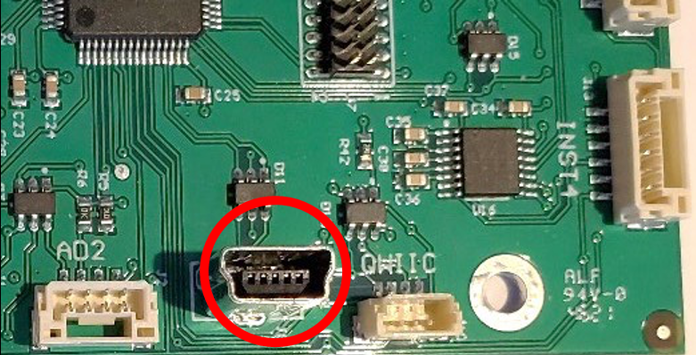
Note: Typically, your computer will notify you when it creates a new COM port and identify the number. If not, you can identify the port in the Device Manager, or simply try all of the COM ports in the list.
Caution: To ensure the enclosure meets ingress standards after disassembly, confirm that the gasket is positioned correctly between the two halves, and then tighten the four screws. Double check the tightness of each screw before deploying outdoors.
Using the radio serial port
The radio port can be connected to a personal computer or a computing device that supports UART, such as a data logger, Raspberry Pi, or BeagleBone®. See Connecting a GPS receiver or radio transceiver for cable assembly instructions and Radio port for port settings.
Data and menus
When the LI-570 is connected to a terminal emulator, the data stream will scroll up the screen. This is normal Sampling Mode. If an SD card is installed in the LI-570, the data are saved to a file on the card until you enter Menu Interface Mode.
Caution: When the LI-570 is in Menu Interface Mode (MIM) all data sampling is stopped, and the storage file is closed. All incoming data are lost when in Menu Interface Mode.
- Press ESC on your keyboard to enter Menu Interface Mode. The main menu will load on the terminal emulator screen (see Main menu).
- Press X to discard changes and exit Menu Interface Mode.
- Press 0 (zero) to store changes and exit Menu Interface Mode.
- Press Ctrl + C to stop the data stream and enter the command-line interface (see Configuring with the command-line interface).
- Type exit to return to Sampling Mode.
- Type help to view the menu (see The Help menu).
Main menu
The Menu Interface Mode main menu lists sub-menus for configuring equipment function and data stream settings.
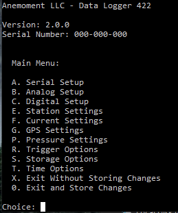
To enter a sub-menu, press the letter key to the left of the option. A sub-menu lists available options for a specified function. Information in the parentheses to the right of each option shows the current configuration status.
Press 0 (zero) to return to the main menu from a sub-menu (changes will be stored). Press the letter key to the left of the option to make changes to that configuration.
Depending on the type of variable, pressing the letter key may result in a toggle selection, a cycle selection, a text entry prompt, or a new multiple choice sub-sub-menu.
- Toggle selections are used where there are only two configuration options for the selection. Pressing the letter key causes the information inside the parentheses to the right to change between the two possible configurations: i.e.,
enabled/disabled. - Cycle selections are used where there are three or more options for the setting. Pressing the letter key changes the setting and the information inside the parentheses. For some options, the information in the parenthesis changes and an additional sub-menu is presented. Press the letter key to make a change to that configuration option.
- Text Entry prompts let you enter a text value. Press enter to complete the text entry.
- Multiple Choice sub-menus are used when there are several configuration options for the selection, or when the configuration options apply to more than one attached instrument. Pressing the letter key causes a new sub-menu list to appear. Press the letter or number key indicated to the left of the configuration option to make changes to that configuration. When in a multiple choice sub- or sub-sub-menu and no further changes are desired, press 0 (zero) to return to the previous menu.
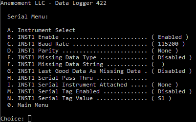
Serial setup
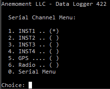
This menu presents configurations for each of the six serial instruments that may be connected to the LI-570: Instruments 1 through 4, the GPS receiver, and the radio transceiver.
| Menu Option | Description |
|---|---|
| Instrument Select | Presents a secondary menu to define which Serial Instrument is being configured. In the example, INST1 is being configured. |
| Enable | Toggles the Serial Port Enable setting. This turns on the data sampling for the port |
| Baud Rate | Presents a secondary menu to choose the baud rate |
| Parity | Presents a secondary menu to choose the parity |
| Missing Data Type | Toggles the Missing Data Type setting. When Missing Data Type is enabled, the LI-570 fills in false data when the instrument data is missing. The values filled in are either the value in the Missing Data String field or the last good data received from the instrument. |
| Missing Data String | User entered text string that is substituted for instrument data when Missing Data Type is enabled and Last Good Data as Missing Data is disabled. |
| Last Good Data as Missing Data | Toggles the Last Good Data as Missing Data setting. When this setting is enabled at the same time as the Missing Data Type function, the LI-570 overrides the Missing Data String value. |
| Serial Pass Thru | Presents a sub-menu for the serial pass thru functions. Serial pass thru makes a direct connection with the instrument using the LI-570 as a bridge between the computer and the instrument. In the sub-menu is a command to allow you to select a character to exit the pass thru mode. When you enter this character (Default = Ctrl+D) the Serial Pass Thru mode is terminated and control returns to the LI-570. |
| Serial Tag Enabled | Toggles the setting for a serial tag that is placed in the data stream in front of the instrument data. The value inserted is contained in the serial tag value below. |
| Serial Tag Value | The text string that is inserted in the data stream in front of the instrument data when the serial tag is enabled. |
To change the way data are recorded from a serial instrument:
- Press a letter key to select an instrument (A to select an instrument port to configure).
- The display will show a sub-menu of instruments and ports, including INST1, INST2, INST3, INST4, GPS, or radio (see ).
- Press the key indicated to the left of the desired instrument.
- The terminal program will return to the Serial Setup Menu and present the options for that instrument.
Analog setup
Analog inputs are not supported at this time.
Digital setup
Digital inputs are not supported at this time.
Station settings
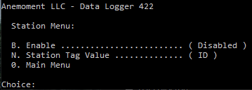
Station Settings control the display of the Station ID output, to identify this LI-570 among multiple data loggers. The Station ID can be up to 40 characters long.
| Menu Option | Description |
|---|---|
| Enable | Enable or disable displaying Station Tag. |
| Station Tag Value | The text string that is inserted in the data stream in front of the Station channel data when the Station Tag is Enabled. |
Current settings
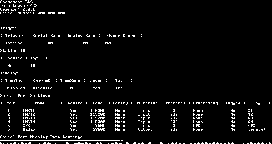
Current Settings displays a list of the current configuration settings. From the Main Menu, press F to view the settings. This is a simple way to see details about your data logger, including the serial number, firmware version, and more.
GPS settings
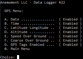
The GPS Menu presents options for the GPS parameters in the output.
| Menu Option | Description |
|---|---|
| Date | Display the GPS data in the GPS output. |
| Time | Display the GPS time in the GPS output. |
| Latitude Longitude | Display the GPS latitude and longitude in the GPS output. |
| Altitude | Display the GPS altitude in the GPS output. |
| Speed Over Ground | Display the GPS speed over ground in the GPS output. |
| Coarse Over Ground | Display the GPS course over ground in the GPS output. |
| GPS Tags Enabled | Enable or disable the parameter tags in the GPS output. |
Pressure settings
The Pressure Menu presents options for the on-board pressure sensor and tag.
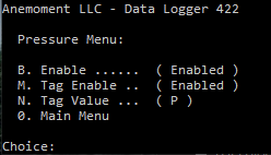
| Menu Option | Description |
|---|---|
| Enable | Enable the onboard pressure sensor output. |
| Tag Enable | Enable the onboard pressure sensor tag in the output. |
| Tag Value | Set the Tag value for the pressure sensor output. |
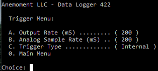
Trigger options
The Trigger Menu controls the sampling rates and trigger sources for the LI-570.
| Menu Option | Description |
|---|---|
| Output Rate |
This value is the number of milliseconds between data output samples. The most recent values from the instruments are presented in the output. If the instrument is providing data faster than the sample rate, only the most recent value is provided. If the instrument is providing data slower than the sample rate, then the missing data options from the serial menu can be used to set what data is inserted into the output data stream. |
| Analog Sample Rate |
This value is the number of milliseconds between internal analog samples. If this value is smaller than the output rate, the samples are averaged until the output rate time is reached. If this value is larger than the output rate, the most recent analog sample is provided. |
| Trigger Type |
The LI-570 supports two trigger types: Internal and Sync. Internal: When set to Internal, the LI-570 uses its internal clock to sample the data for output. Sync: The Sync trigger aligns the internal clock to the edge of the sync trigger. This is useful for using an external time standard to synchronize multiple sampling stations. |
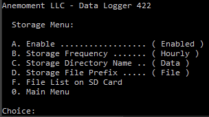
Storage options
The Storage Menu shows settings to control how the LI-570 logs data to the MicroSD card.
| Menu Option | Description |
|---|---|
| Enable | Enable the logging of data to the MicroSD card. |
| Storage Frequency | Sets the time frequency for when a new file is started. The frequency choices are weekly, daily, hourly, half-hourly, and quarter-hourly. New files start at the beginning of the time period (according to the LI-570 internal clock). |
| Storage Directory Name | This is name of the directory where the data files will be stored. This directory is created in the root directory of the MicroSD card. |
| Storage File Prefix | This text string is prefixed to the time tag to create the filename. |
| File List on SD card | List the file names of the files that are in the storage directory. |
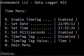
Time options
The Time Menu provides all the options to enable and configure the time settings of the LI-570. If GPS data are available, the GPS time and date are used to generate the time and date. When the GPS data are not available, the internal real time clock (RTC) of the LI-570 is used.
| Menu Option | Description |
|---|---|
| Enable Time Tag | Enable the time tagging of data for the output stream and logging. |
| Set Date | Set the data logger date. |
| Set Time | Set the data logger time. |
| Set Milliseconds | Enabled the milliseconds output in the time tag. |
| TimeTag Tag | Enable the tag that precedes the time tag output. |
| TimeTag Tag Value | Set the value of the tag the precedes the time tag output. |