
Humidity Control
Humidity control in the LI-6400 is done by a combination of two mechanisms:
- Incoming humidity
- The mechanism for controlling incoming humidity is manual: the amount of incoming air that is routed through the desiccant is set by the valve on the top of the desiccant tube, allowing incoming humidities to range from ambient to dry. (You could also moisten the air - see Humidifying Incoming Air.)
- The flow rate of air through the chamber
- The flow of air through the chamber is controlled by the software, either by controlling pump speed (CO2 mixer not installed) or diverting excess flow (CO2 mixer installed).
The Operational Envelope
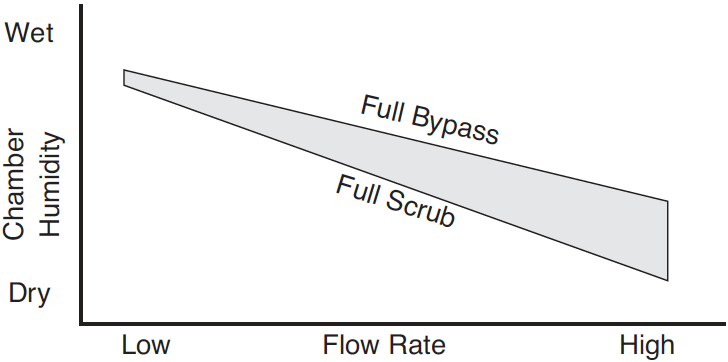
The manual bypass control defines the operating envelope within which the automatic flow controls can operate. By forcing more of the flow through the desiccant, the operating window (upper and lower limits of humidity) decreases; when less air is forced through the desiccant, the window increases (Figure 7‑6).
Control Options
When f2 level 2 is pressed in New Measurements mode, the following control options are presented:
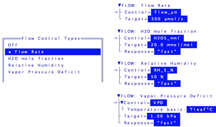
| Option | Description |
|---|---|
| Off | Turns off the pump. Not normally used, except for diagnostics, or to save the battery or motor when not taking measurements. Or, to provide some peace and quiet. |
| Flow rate | Maintains a fixed flow rate through the chamber. This is a good default option. |
| H2O mole fraction | Maintains a constant water mole fraction in the sample cell. This is useful during response curves for light or CO2. |
| Relative humidity | Maintains a constant relative humidity in the sample cell. |
| Vapor pressure deficit | Maintains a constant vapor pressure deficit in the sample cell. This VPD can be based on a leaf or air temperature (you choose the variable). |
For best results, start off using the Flow rate option, at a mid-range flow rate (400 μmol s-1). Then, adjust the desiccant knob as necessary to give the desired humidity in the chamber. You may have to modify the flow rate to achieve a particular humidity. For example, if you can not get the humidity high enough at 400 μmol s-1 even with the desiccant on full bypass, then slow the flow down.
High flow rates are good from a system response point of view, but reduce the CO2 and H2O differentials on which the calculations are based. Low flow rates will increase these differentials, making their measurement less prone to error, but at the cost of increasing the system response time. Try to keep the flow rates above 100 μmol s-1 (without a CO2 mixer installed) or 50 μmol s-1 (with a mixer installed).
Constant Humidity Operation
The mole fraction, relative humidity and VPD options actively regulate the flow rate to maintain a constant humidity (either water vapor mole fraction, or relative humidity, or vapor pressure deficit) in the sample cell / leaf chamber.
Note: For constant humidity options to work well, the leaf must be supplying a reasonable source of humidity. Thus, small leaf areas, low transpiration rates, or an empty leaf chamber, can make these options problematic.
The leaf chamber water vapor concentration that can be maintained is dependent upon a number of factors, including the transpiration rate of the leaf, the vapor pressure of the incoming air stream, and the volume of air that is being diverted through the desiccant tube.
For best results with constant humidity options:
- Start out with the constant flow rate option
- Manually find the flow rate / desiccant tube setting that provides the desired humidity or vapor pressure deficit.
- Switch over to the humidity option
- Your target value will be close to what is actually being achieved, so the control system will not have to do very much to get it there and hold it there.
H2O Mole Fraction
Constant mole fraction is a fairly tight control circuit. The work is done by hardware circuitry, so no software intervention is needed. The software does figure out what signal (mV) the sample cell water IRGA will be putting out when the mole fraction is at the target value; this is communicated to the control circuit via an analog output signal. Since this target signal is also a function of pressure, temperature, and how the IRGA is zeroed and matched, there needs to be periodic updates of this target signal, even when the target mole fraction does not change.
Relative Humidity
The constant RH control is a simple extension of the H2O mole fraction mode. The actual control is the same, it is just that more frequent updates are needed, since temperature is now in the mix. If temperature is changing rapidly, the temperature updates may not be frequent enough, and the actual RH may drift off target a little bit (usually not more than a couple of percent).
Vapor Pressure Deficit
This is the difference in vapor pressure between location X and what is actually in the air. Where is X? Well, you have at least two options: the chamber air, or the substomatal cavity of the leaf. In the case of the former,
7‑1

and in the case of the latter,
7‑2

where e(T) is the saturation vapor pressure function (Equation (14-24) on page 14-13 in the instruction manual), Tca is computed chamber air temperature, ID# 225 (defined in the StdComps_6.2 ComputeList file)1, Tl is leaf temperature, and es is vapor pressure in the sample cell (Equation (14-21) on page 14-12 in the instruction manual). The constant VPD option is the loosest humidity control, especially for VPD with respect to leaf temperature. The reason is that the only thing the humidity control has to work with is the flow rate, while there are a number of other things directly affecting the air or leaf temperature, such as incident radiation, transpiration rate, etc.
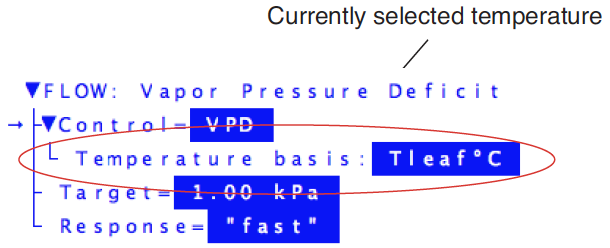
When you select the Vapor Pressure Deficit option, there will appear a subnode named Temperature basis (Figure 7‑8). This determines the temperature used in the calculation of VPD. value, followed by a temperature.
When you edit this node, you are shown a menu of all user defined variables, and two system variables: Tleaf°C and Tair°C. (Figure 7‑9).
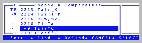
The reason the menu in Figure 7‑9 includes all user variables is to allow you to select a temperature that you may be measuring or computing besides the two system temperatures. Normally through, you would select either Tleaf°C or Tair°C. Don’t make the mistake of selecting VpdL or VpdA. Remember, you are not selecting a VPD value, you are selecting a temperature for the system to use for its own VPD calculation.
Humidity Time Response
When one of the constant humidity options is active, the setup dialog will include a Response node.
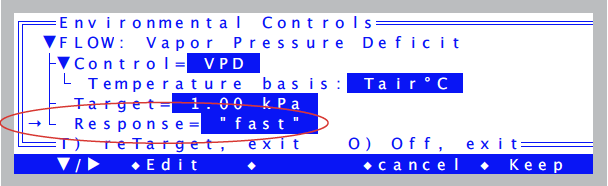
When edited, the time response will cycle between fast, medium, and slow. This determines the rapidity of response of the control circuit (see Figure 3‑38). The fast setting will give you tight humidity control, but at the expense of “jumpy” flow readings. This is best for survey measurements when you are doing humidity control, and want to lock in rapidly on the target humidity as you go from leaf to leaf. The medium setting will drop the variability of the flow in half and still do a reasonable job of maintaining humidity on target. This is best for response curves and AutoPrograms, when you would like stable flow readings and stable humidities, and are not expecting abrupt changes in incoming humidity or transpiration rate. The slow setting is not particularly useful, unless you want the smallest possible flow variations and are not expecting any appreciable excursions in transpiration rates or incoming humidities.