
Making Measurements
The procedure below lists the steps required to make a soil surface CO2 flux measurement. It is assumed that the LI-6400 sensor head has already been attached to the chamber (Attaching the Soil Chamber to the Sensor Head), and that the system has been configured for use with the chamber (Configuring OPEN for Soil Measurements).
There are two different methods of making measurements. The 6400-09 can be inserted directly into the soil for measurements, or it can be used with soil collars that are inserted into the soil.
Usually, it is preferable to use collars, since inserting a ring (collar or chamber) down into the soil will create artificial flux rates for (potentially) hours afterwards. Collars, once installed, avoid this, allowing the possibility of repeated measurements (chamber on - several cycles - chamber off) at one location. Direct insertion of the chamber, on the other hand, is essentially a destructive, one-time measurement. Perhaps the only advantage of not using collars are those of versatility and spontaneity in choosing measurement locations, and the avoidance of long-term microclimate changes that are likely with long-term collars.
Measuring With Soil Collars
Soil collars should be installed several hours to one day before making a measurement. You can test to see if the flux has stabilized by making a measurement immediately after installing the collar, and then make subsequent measurements over time. Note, however, that the soil surface CO2 flux depends on the time of day, and the diurnal cycle can be quite large. Care must also be taken not to let the bottom edge of the chamber disturb the soil surface within the collar. However, the chamber edge should be as close to the soil surface as practical so that air flow within the chamber produces mixing near the soil surface. Adjust the stop ring to position the chamber near the soil surface. Use a foam gasket between the bottom of the stop ring and the top of the soil collar to minimize leaks between the collar and the chamber.
The soil area value should be set to 80 cm2 (or whatever is appropriate based on the collar diameter).
Measuring Without Soil Collars
The chamber should be installed on the soil surface by pressing gently and firmly straight down on the mounting plate without rotation. Rotating the chamber may disturb the soil surface by creating a gap around the inside of the chamber, allowing CO2 in the soil to escape. The soil surface should not be disturbed at all immediately before the measurement. If the surface must be cleared or smoothed before measurements can be made, it should be done prior to the measurement; preferably hours for minor alterations and a day for severe alteration.
Before you start
- Position the Air Supply Manifold
- Move the lower air supply manifold up or down inside the chamber body so that it is 1-2 cm above the soil surface, regardless of whether or not soil collars are being used for the measurement. This will ensure proper mixing of air coming from the IRGA
- Check Hose Connections
- Make sure the plumbing is connected as shown in Figure 28‑5, and especially that the two short pieces of tubing in the Y connector are fully seated (Figure 28‑17).
The Measurement Sequence
- Determine the CO2 concentration of the air near the soil surface.
- To do this, lay the chamber on its side and monitor soil chamber CO2 concentration (CO2S_μml). You may want to fan ambient air into the chamber (no exhaling, please) if there is little or no wind.
- Install the 6400-09 at the measurement location.
- Insert the soil temperature probe to an appropriate depth (typically 5 to 10 cm) near the Soil Chamber.
- Set Target and Delta
- In New Measurements mode, press f1 level 7 to set the Target and Delta values. Use the ambient CO2 concentration determined in Step 1 as the Target, and choose a Delta appropriate for your site. For low rates, the Delta should be 5 or 10 ppm. For higher rates, the delta will have to be increased.
- Enter the insertion depth of the chamber
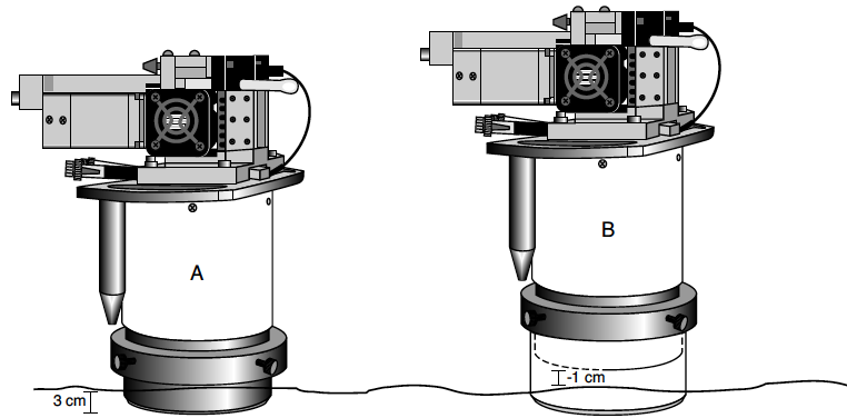
- If inserting directly into the soil, InsDepth will be a positive value, such as 1 or 2 cm, depending on the soil type and the Stop ring position (A in Figure 28‑30). With soil collars (B Figure 28‑30), this will be a negative number that is equal to the distance in cm between the bottom edge of the soil chamber and the soil surface.
- To enter the insertion depth value, press f5 level 7.
- Enter the number of cycles
- The number (NumCycls) of cycles the instrument should perform at any given location is entered via f2 level 7.
- Select what you want stored in the log file
- Press f4 level 7 and select whether you want to save final computed values, intermediate instantaneous observations, or both.
- Set prompts?
- If you wish to be prompted for some things (location, Area, InsDepth, etc.) automatically at the start of each measurement, set that up by:
- Prompt Control in the Config Menu to set up the item list.
- f4 level 3 to turn Prompts to OnLog.
- Start the measurement
- Press Start (f3 level 7). If you have Prompts ON, you will get those now. Then, you will be prompted to enter a name for the log file if one is not already open. If you don’t wish to create a file, press escape instead, then press escape again when asked about logging to the Comm port.
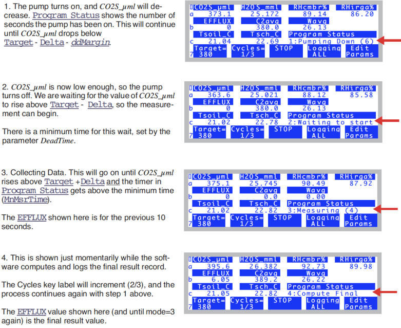
The measurement cycle will begin (Figure 28‑31).
Real-time Graphics
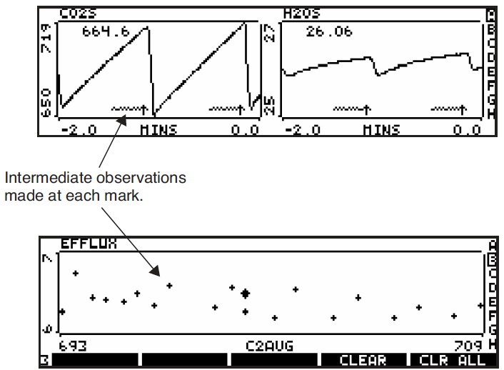
The default soil chamber configuration has some Real Time Graphs (Real Time Graphics on page 6-14 in the instruction manual) defined that are useful (Figure 28‑32). You can monitor the time series of CO2, and the relationship between flux and CO2 concentration, among other things.
AutoPrograms
The typical AutoPrograms (such as AutoLog) are not necessary with the soil chamber, since the measuring routine is built into the events triggered by pressing Start (f3 level 7). However, there is one program -“Soil Efflux vs CO2” - that is added to the programs stored in /User/Configs/AutoProgs when the soil CO2 flux configuration is created. This program lets you specify a range of target values to be measured automatically. You launch this program like any other (see AutoPrograms on page 9-31 in the instruction manual), and it will set the targets and begin the measurements automatically to cover the range you specified.