Installing the large leaf chamber
Printable PDF: Installing the large leaf chamber
(6800_InstallGuide_6x6cm_Leaf_Chamber_16473.pdf)
Download this content as a pdf that can be saved to your computer or printed.
The 6×6 cm chamber is used for large leaves. This document describes how to install it on the LI-6800 head.
Attaching the chamber
See Removing a chamber to detach a chamber.
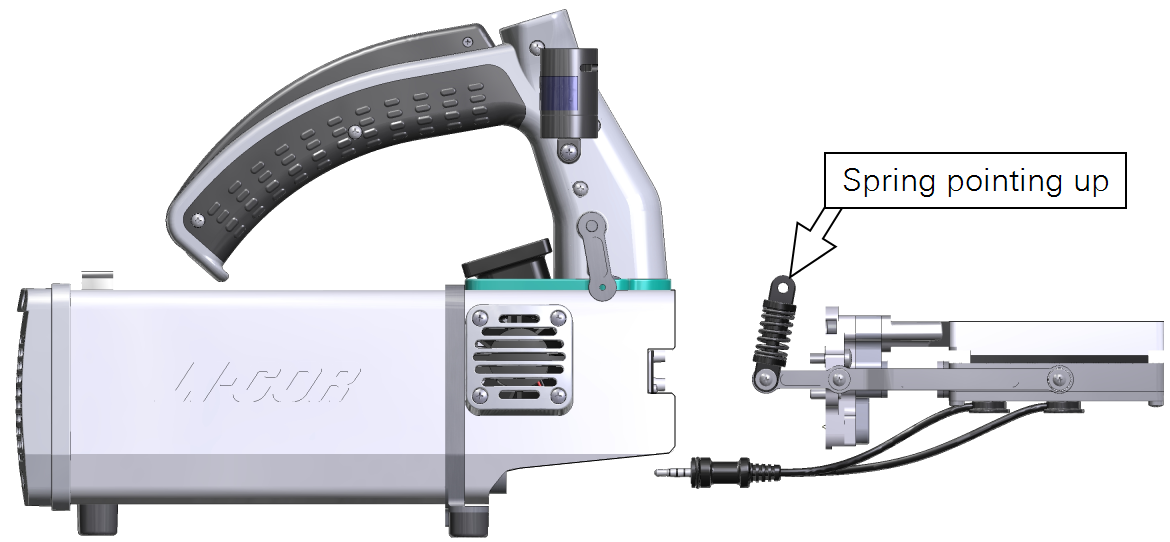
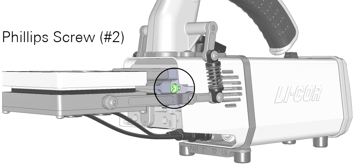
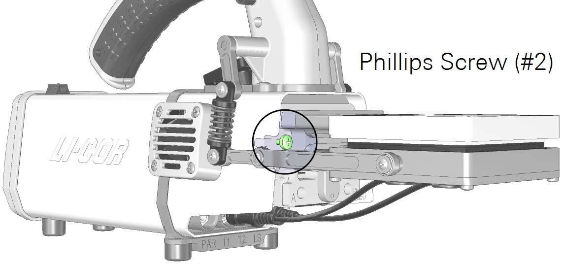
- Hold the chamber in position, with the latch springs up toward the handle, and tighten the two captive chamber screws (146-15344).
- Use the #2 Phillips screwdriver from the spares kit. Suitable screwdrivers also are available from most departments stores.
- Caution: Use the captive chamber screws (part number 146‑15344) to install the chamber. Other screws will cause leaks and problems with the mixing fan.
- Make them snug—turn each screw until it stops, and then just a little bit more (up to ¼ turn). If you have a torque screwdriver, tighten them to 2.5 N·m (22 inch lbs).
- Install the latch screws.
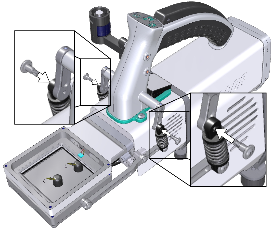
- With the latch open, tighten until they are snug. If you have a torque screwdriver, tighten them to 1.1 N·m (9.4 inch lbs).
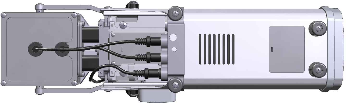
- If you unplugged the light sensor cable, install the light sensor connector to the connection labeled PAR.
- Install the leaf temperature thermocouple connectors to the connections labeled T1 and T2.
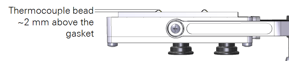
- Adjust the thermocouple height.
- Install the connector cover.
After swapping chambers, it is a good idea to verify that the chamber is sealed and that the software recognizes it. Run the leak test under Start up > System Tests > Chamber Leak. Check to see that the chamber is recognized under Constants > System Constants > ChType.
Connecting the large light source
The 6×6 cm light source attaches directly on top of the 6×6 cm Clear-top Chamber, Bryophyte Chamber, or Small Plant Chamber.
 Warning: The light sources for this product can emit potentially hazardous optical radiation (RG-2 CAUTION POSSIBLY HAZARDOUS OPTICAL RADIATION EMITTED FROM THIS PRODUCT), in excess of the Exempt Risk Group. Potential risk depends upon how one uses and installs this product. Do not operate the light source while detached from the chamber. Do not look directly into the light source under any circumstances. Operate the light sources with direct access to ambient air for cooling. Do not use the product in any manner not described in the manual.
To install the light source:
- Install a compatible chamber on the LI-6800: either the 6×6 cm leaf chamber, small plant chamber, or the bryophyte chamber.
- Check the chamber top Propafilm for dirt or damage.
- Clean or replace it if necessary.
- Check the light source window for smudges or fingerprints.
- Wipe it with a soft cloth or alcohol swab if necessary.
- Install the light source adapter plate on the chamber top.
- Tighten the screws (part number 150-07475) snugly—until the screw stops, then just a little bit more (up to ¼ turn).
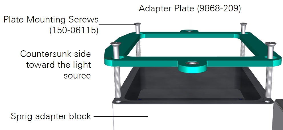
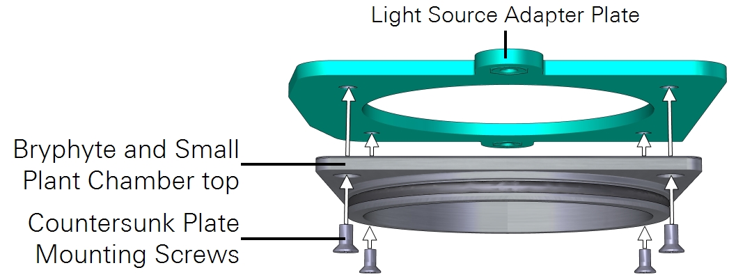
- Install the light source on top of the adapter.
- The square corner of the adapter plate should be aligned with the cable.
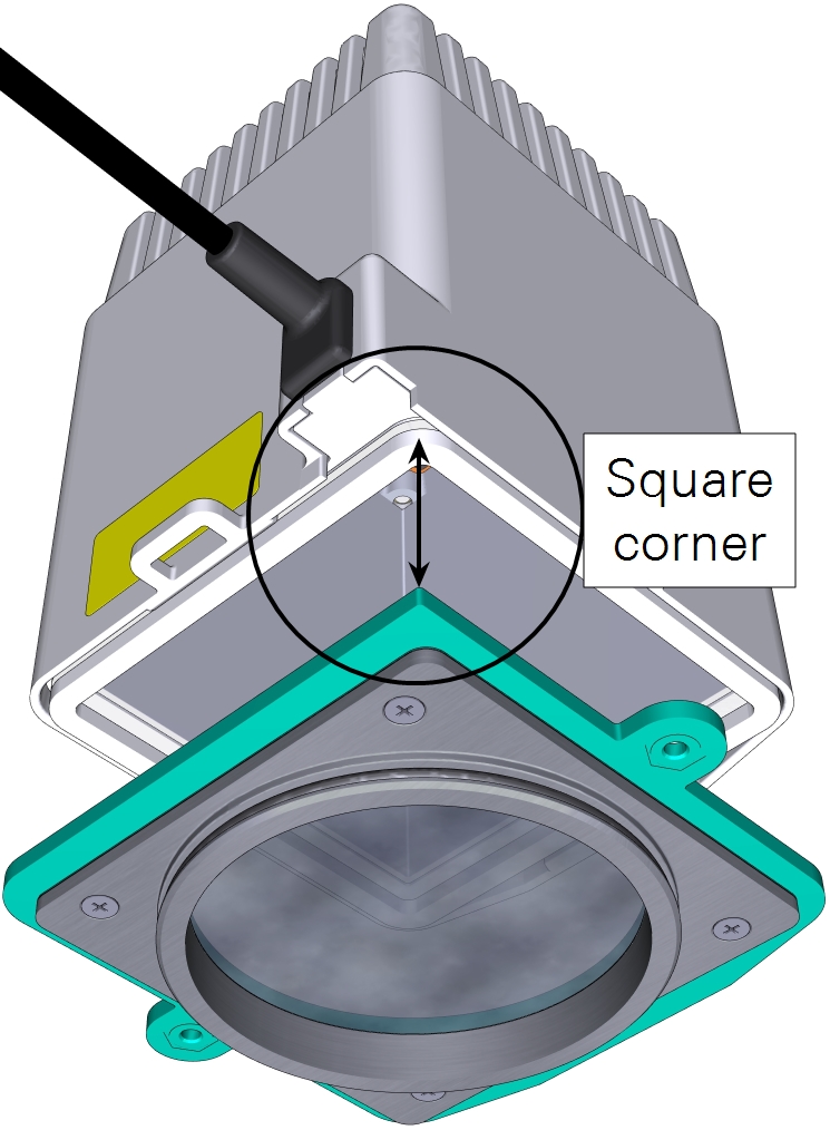
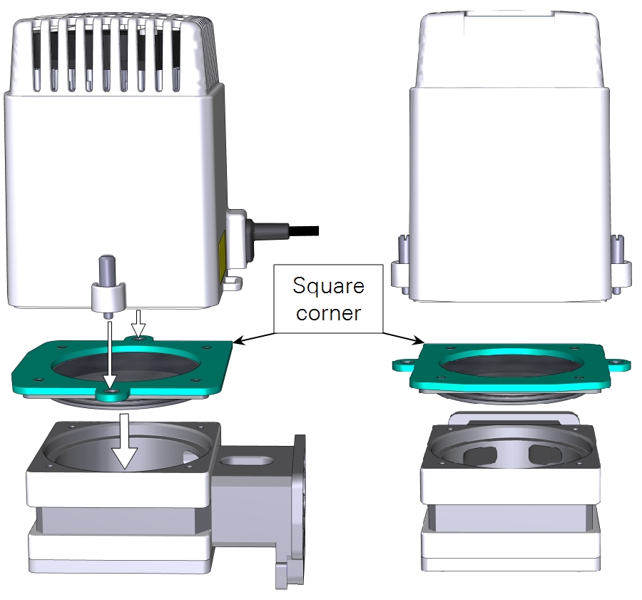
- Position the light source over the chamber, then tighten the two knurled captive screws until they are tight.
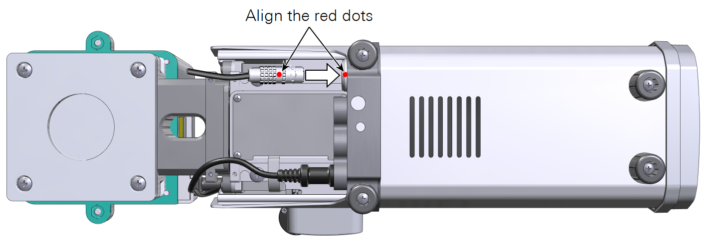
- Plug in the cable connector.
- Remove the connector cover, then route the cable between the chamber arm and duct. It connects to the light source connecter (labeled LS) under the connector cover. Align the red dots on the connectors. Reinstall the connector cover.
- Turn the light source software switch ON.
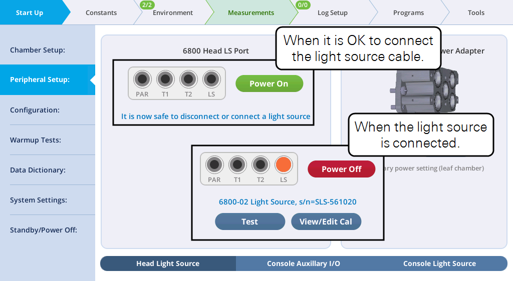
- Check the light source under Start Up > Peripheral Setup > Head Light Source. The instrument should detect the light source and power it on automatically a few seconds after it is connected.
- Check the response.
- Under Environment > Head LS, set Head LS to Setpoint, and set the Q Setpoint to 200 µmol m-2 s-1. Open the chamber and look at the light that shines onto the chamber bottom (never look directly into the light sources).
- If this is your first time using the light source, adjust the Red, Green, Blue, and White light ratios to get a sense of how they work. Then set Red: 9 and Blue: 1 to provide 9 parts red and 1 part blue, which is a typical ratio for gas exchange measurements.
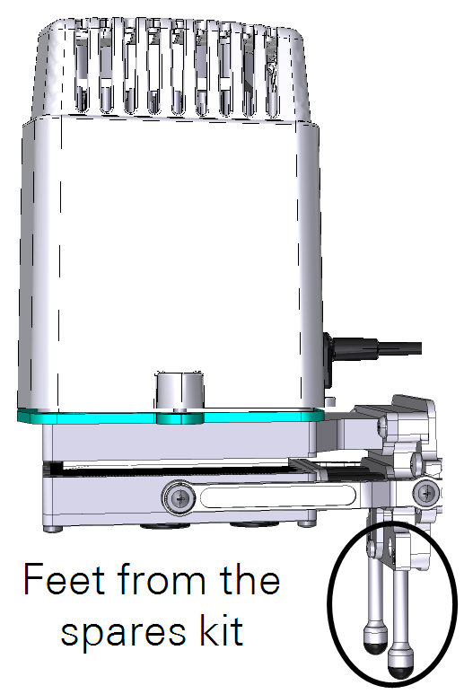
For laboratory applications, where the instrument head sits on a bench, install the two chamber feet from the spares kit (part number 9968-253) to prevent the head from tipping over. We do not recommend the feet for field measurements because they can be damaged by inadvertent impacts.