Using a pH probe
The aquatic chamber can read analog measurements from a standard glass pH electrode through the BNC connector on the side of the chamber (10 in Figure 10‑2). The pH electrode is inserted into the sample cuvette through the O-ring-sealed port on the side of the aquatic chamber (13 in Figure 10‑2). It fits a standard 12 mm diameter probe.
pH is computed from
10‑86


where pHn is neutral pH (typically 7), Vn is the pH probe's signal at neutral pH (typically 0 V), V is the pH probe's signal (V), F is the Faraday constant (96485.309 C mol-1), S is the calibration slope factor (typically close to 1.0), R is the universal gas constant (8.314510 J mol-1 K-1), and Taq is the temperature of the sample cell.
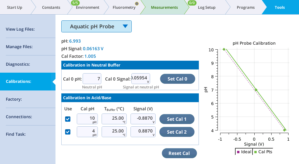
Computations of pH are included in the GasEx group. A pH probe calibration screen is presented in Tools > Calibrations. Several of these parameters come from the calibration screen (Figure 10‑25), which allows for a 0-, 1-, 2-, or 3-point calibration.
Adjusting the calibration
For a 0-point calibration, simply tap the Reset Cal button. The pH probe response will then be entirely idealized: 0 V will correspond to a pH of 7, and cal factor (S in equation 10‑87) is 1.0.
For a 1-point calibration, dip the probe into a neutral pH buffer. If the true pH isn't exactly 7, edit the values in the Cal 0 pH edit box. Tap the Set Cal 0 button record the signal. A 1-point calibration shifts the response curve left or right to intersect the cal point at neutral pH, but still has a calibration factor (slope) of 1.0.
For 2- or 3-point adjustments, first do the 1 point calibration. Then use one or more known pH buffers, entering the pH value in the edit box, and tapping the corresponding Set Cal 1 or Set Cal 2 button when the probe is equilibrated. Check the box to actually enable the calibration point. A new slope is then computed. If two non-neutral points are used, the slope will be the best fit between them, always going through the neutral calibration point.
| Group | Label | Description |
|---|---|---|
| pH cal | Cal 0 pH | pHn in equation 10‑87. Set in the calibration screen (Figure 10‑25). |
| Cal 0 signal | Vn in equation 10‑87. Set in the calibration screen. | |
| Use cal 1 | Corresponds to the Cal 1 check box in the calibration screen. | |
| Cal 1 pH | The value in the Cal 1 pH edit box in the calibration screen. | |
| Cal 1 signal | The value in the Cal 1 signal edit box in the calibration screen. | |
| Cal 1 T | Set in Cal 1 Tbuffer edit box in the calibration screen. | |
| Use cal 2 | Corresponds to the Cal 2 check box in the calibration screen. | |
| Cal 2 pH | The value in the Cal 2 pH edit box in the calibration screen. | |
| Cal 2 signal | The value in the Cal 2 signal edit box in the calibration screen. | |
| Cal 2 T | Set in Cal 2 Tbuffer edit box in the calibration screen. | |
| Cal factor | S in equation 10‑87. Displayed as Cal Factor in calibration screen. | |
| GasEx | pH signal | V in equation 10‑87. Comes from Auxiliary:ADC CH8 |
| pH | pH - the computed pH (equation 10‑87) |
Orientation considerations
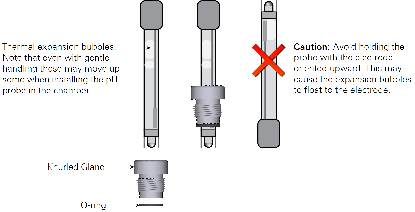
Few pH probes are specified for long-term operation in the orientation of the probe port in the aquatic chamber. Most gel filled pH probes include an air bubble in the electrolyte solution to compensate for thermal expansion of the fluid. For these probes, the slight upward orientation of the probe may cause this bubble to migrate upward where it can contact the reference membrane or the glass electrode itself. Without fluid contact on both sides of either the membrane or electrode, the probe will not function correctly. Probes using a near-solid polymer electrolyte are available that are not susceptible to this issue.
We have found that gel-filled probes do not have problems during typical measurement time frames. In general, once inserted in the chamber the bubble migration is slow and it may take several days for the bubble to move up to a problematic position. Before inserting a gel-filled probe, keep the glass electrode tip pointed downward to ensure the expansion bubble floats as far as possible to the top of the probe. If the bubble moves to the electrode, remove the probe and shake it with the electrode tip point downward to force the bubble to move back up in the probe.
Installing a probe
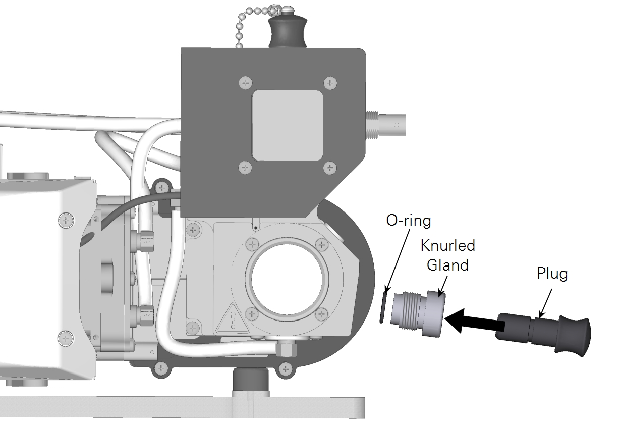
- Remove the knurled gland, plug, and O-ring. Keep them together when pulling them out. The O-ring should be on the plug.
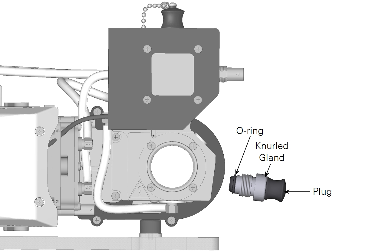
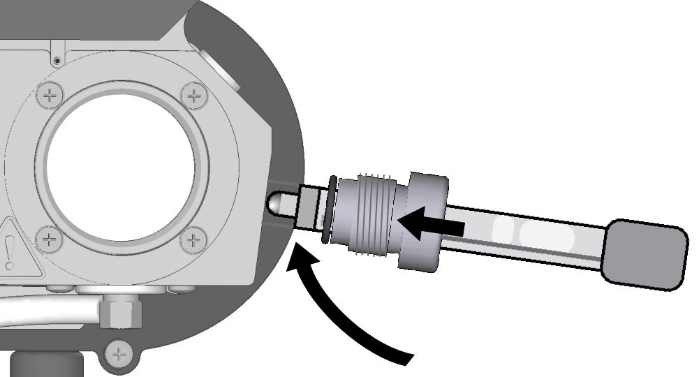
- Hold the pH probe with the electrode tip pointed downward to ensure expansion bubbles float up, away from the electrode. Insert the probe into the knurled gland and O-ring.
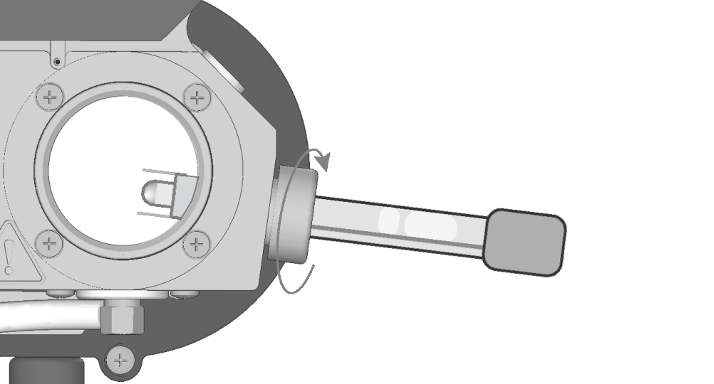
- Slowly rotate the electrode tip up to match the probe port orientation and insert the probe.
- While holding the components in position, turn the knurled gland clockwise. Tighten it snugly to compress the O-ring onto the probe body.
Note: Be sure that the thermal expansion bubbles do not float up to the electrode during measurements. pH measurement errors may result from this.
If the liquid leaks from the port, try tightening the nut to close the leak. If that doesn't work, the O-ring may be dislodged. See Replacing the pH probe port O-ring for more maintenance steps.
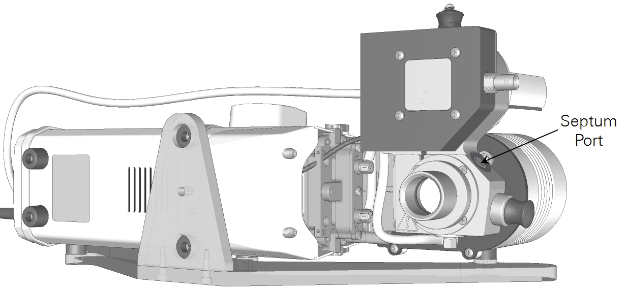
Septum port
A silicone-PTFE laminated septum on the side of the aquatic chamber allows a narrow gauge probe, such as an optode sensor, to be inserted into the sample cuvette. See Replacing the septum for maintenance instructions. Replacement septa (300-08998) are included in the accessories kit.
Important: Leaks from the septum — either air or water — will cause measurement errors. If it is leaking, either tighten the plug or replace the septum.