Maintaining the aquatic chamber
The aquatic chamber will require little routine maintenance. If something goes wrong, this section describes maintenance procedures that you can perform in your lab or office.
Cleaning openings in the orifice plate
Caution: Power off the instrument before following these procedures.
The orifices may become blocked by debris, algae that is left in the chamber, or even a stubborn water droplet. One indicator of blocked orifices is slower than expected response times. You also can observe each orifice in the chamber to see if bubbles are emitted from it. An absence of bubbles indicates a blocked orifice. To clean the orifices:
- Remove any liquid from the chamber and power off the instrument before disassembling the components.
- Turn over the chamber and remove the two screws that secure the cap, PTFE membrane, and orifice plate.
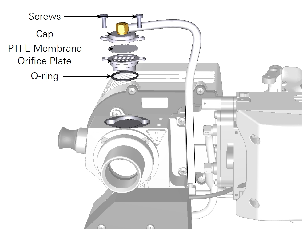
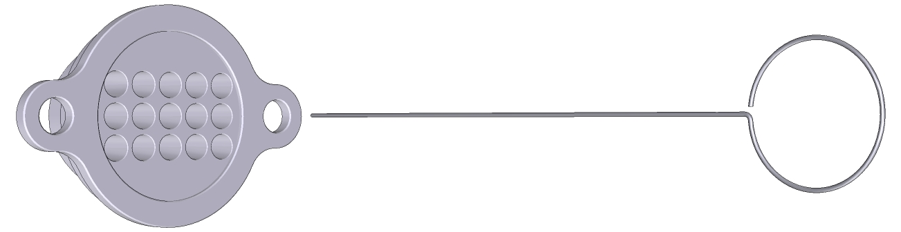
- Use the orifice cleaning tool from the spare parts kit to poke through all of the blocked orifices to clear the blockage. When clear, a pinhole of light will shine through each of the 15 orifices.
- Before reassembly, check the PTFE filter and O-ring for damage. If needed, replace with a new ones from the spares kit (part numbers 6568-658 and 192-18703).
- Reassemble the chamber. The assembly procedure is the reverse of disassembly.
Replacing the orifice plate PTFE membrane
The PTFE membrane below the orifice plate serves as an additional measure to prevent liquid water from flowing freely in the subsample loop. Under some circumstances, the liquid sample may bypass the orifice plate and contaminate the PTFE membrane. This is evident by a green stains on the membrane. Green stains that cannot be removed by rinsing with water indicate that the filter should be replaced. Handle the membrane with clean hands or dust-free latex or nitrile gloves for additional protection.
Cleaning chamber glass
Caution: Power off the instrument before following these procedures.
The glass windows on the sides of the chamber should be clean. Both sides of each window should be free of smudges and deposits. If you observe smudges or deposits on the windows, you can clean them with DI water, glass cleaner, or isopropyl swabs and a soft, lint-free cloth.
- The window on the light sensor side of the chamber is secured with four screws. Pull off the light sensor aperture, and then remove the four screws to remove the window.
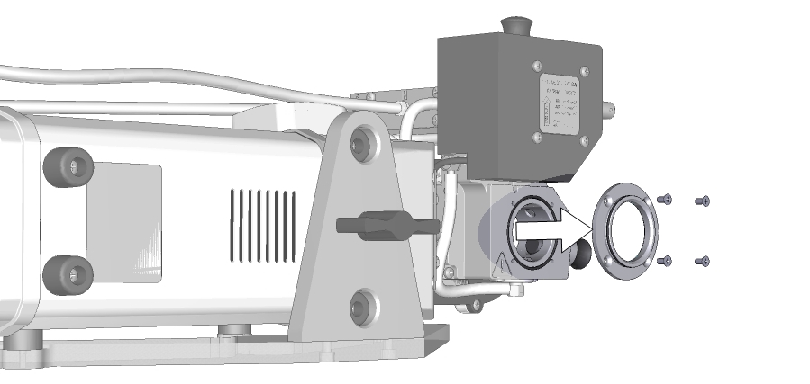
- Clean the window. Check the O-ring for damage and replace it with one from the spares kit if it is torn (38 mm; part number 192-12027). Reinstall it on the chamber. Tighten the screws securely.
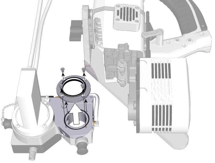
- To access the window on the fluorometer side of the chamber, remove the two screws that hold the aquatic chamber from the fluorometer.

- Rotate the chamber away from the fluorometer.
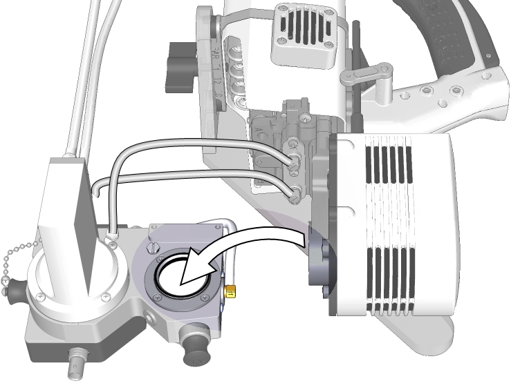
- Then remove the window.
- Clean the both sides of the window.
- Use a soft lint-free cloth. Use deionized water or isopropyl swabs if needed.
- Check the O-ring for damage and replace it with one from the spares kit if it is torn (38 mm; part number 192-12027).
- Reinstall the window on the chamber. Tighten the screws securely.
- Inspect the fluorometer aperture O-ring on the outside of the window.
- If it is damaged, the upper portion of the chamber will not seal and the instrument will fail the start up leak test and give Flow_s Low warnings in the upper left of the display. Replace it with a new O-ring from the spares kit (part number 192-16851) if needed.
- Reassemble the chamber.
Replacing the H2O equilibrator PTFE membrane
Caution: Power off the instrument before following these procedures.
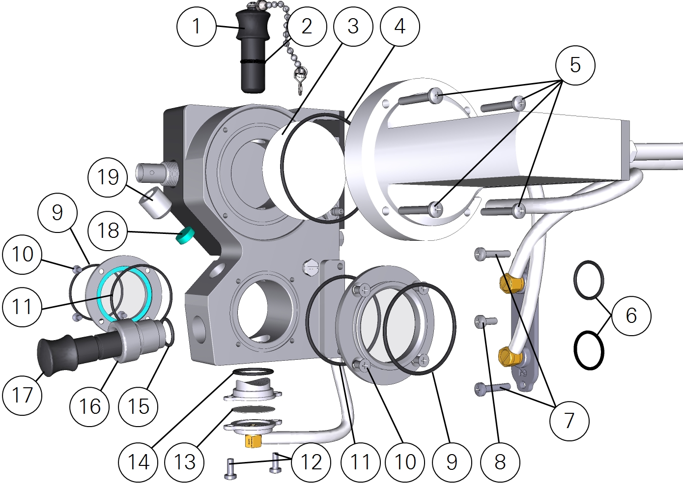
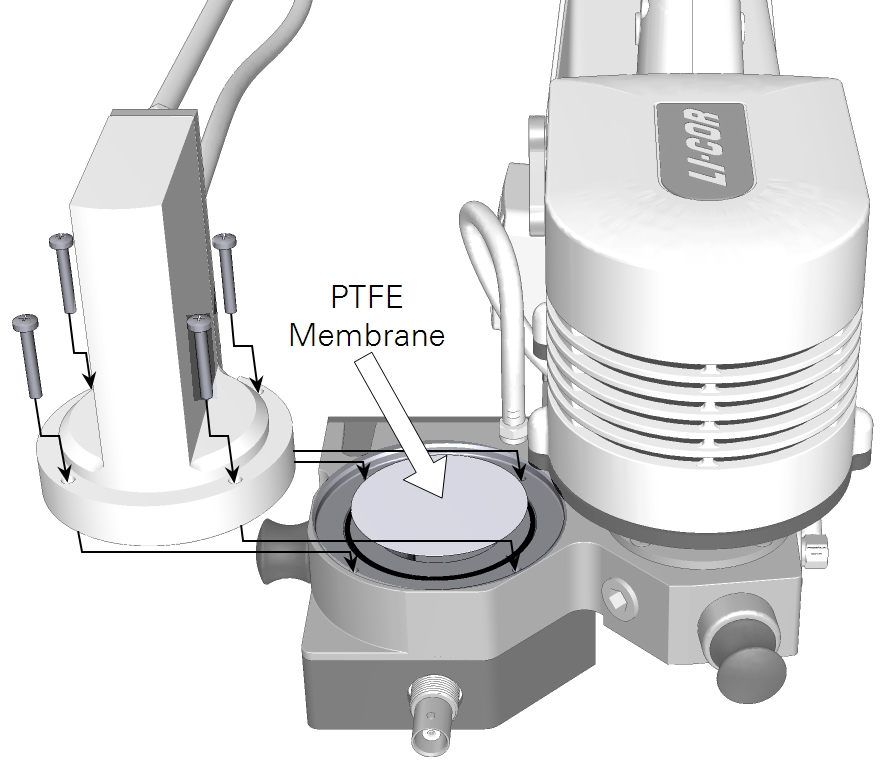
The membrane (16 in Figure 10‑2) that separates the equilibrator can become contaminated by algae if the chamber is not cleaned adequately between samples. Handle the membrane with clean hands or powder-free latex or nitrile gloves for additional protection.
You may want to remove the stand and light sensor aperture and position the head with the equilibrator facing upward (gravity will be your assistant in this orientation). To replace the membrane:
- Remove the four screws that hold the equilibrator to the metal chamber. The PTFE membrane sits over the chamber volume. Lift it out and inspect the side that faces the chamber.
- Check the O-ring for damage and replace it with one from the spares kit if it is torn (48 mm; part number 192-16680).
- Check the membrane for contaminants or damage. Contamination is indicated by discoloration (typically green). If you are unable to rinse contaminants off of the membrane with filtered water, replace it with a new one. Five spare 47 mm membranes are included in the spares kit (part number 301-18701) for this purpose.
- Set a new membrane in place, centered over the opening and O-ring.
- Set the equilibrator in place and tighten the screws securely.
- After reassembling the chamber, run the system tests to ensure that everything is working as expected.
There are no user-serviceable parts in the equilibrator. Do not disassemble it. If water has been forced past the PTFE membrane filter, simply allow the instrument flow pump and subsample pump to run with an empty chamber and dry air until the volume has dried out. Doing so will also dry the Nafion tubing, which may require 30 minutes to rehydrate if is dried out completely.
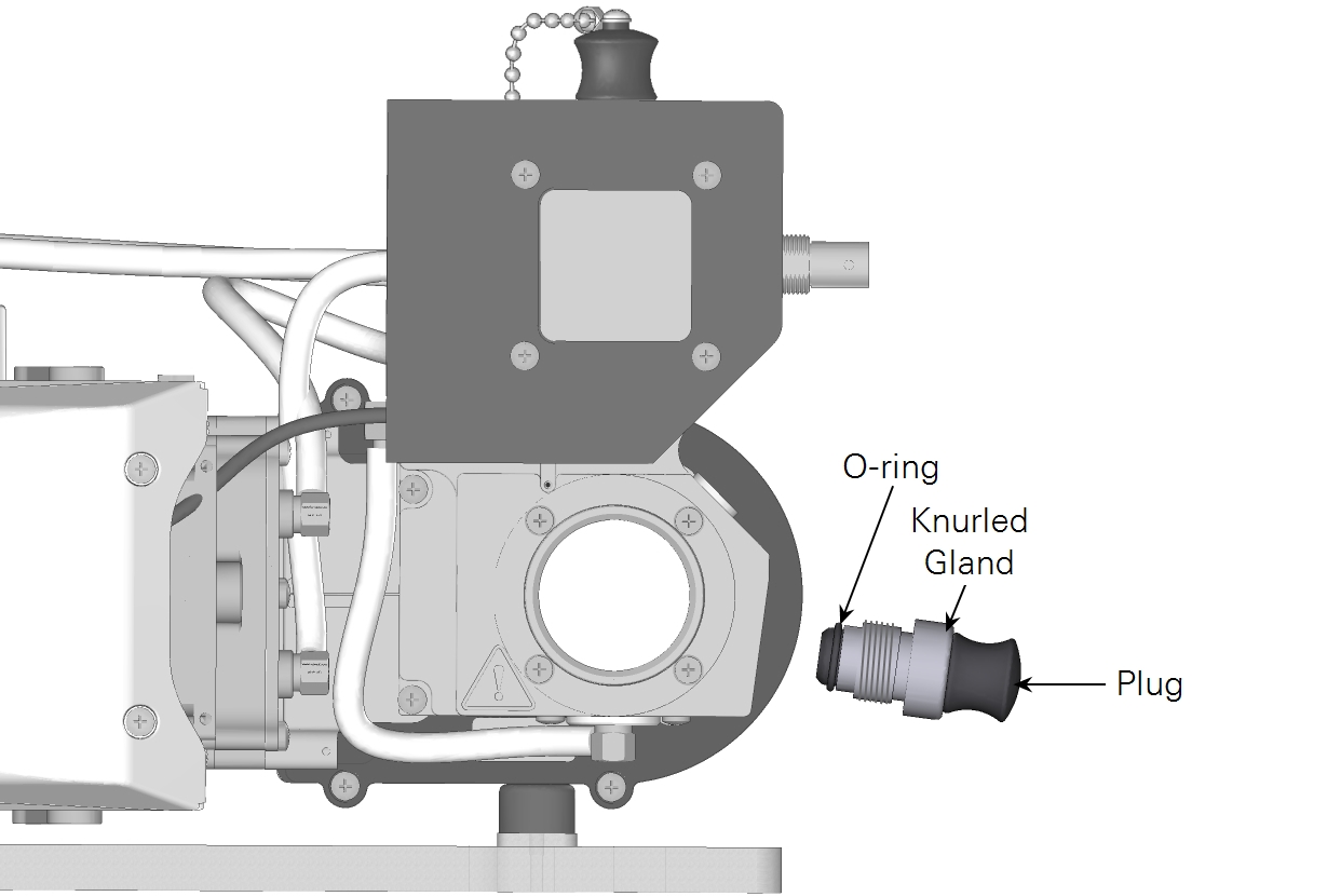
Replacing the pH probe port O-ring
The pH probe port consists of a plug, knurled nut, and O-ring. The O-ring should stay in the port normally. If it comes out, reassemble as shown in Figure 10‑32. Replacement O-rings are in the spares kit (part number 192-18702).
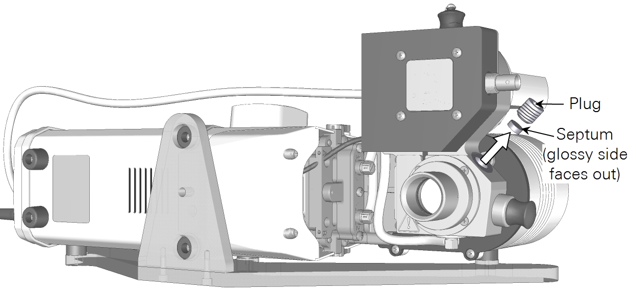
Replacing the septum
If the septum is leaking, it may have a large hole or simply need to be tightened. To replace it, simply remove the plug with a 6 mm hex key. Remove the septum. If it is punctured, insert a replacement from the spares kit (part number 300-08998). The glossy side faces out; the matte side faces into the chamber.
Important: Leaks from the septum — either air or water — will cause measurement errors. If it is leaking, either tighten the plug or replace the septum.
Deep cleaning
Periodically, you may wish to disassemble the chamber to clean surfaces and areas where material may accumulate. Use deionized or filtered water to clean the chamber. A mild detergent and soft-bristled brush such as a toothbrush may be helpful to remove stubborn deposits. Do not wet or immerse the chamber electronics. To clean the chamber:
- Separate the chamber from the fluorometer by removing the two screws that hold it (see Cleaning chamber glass for disassembly instructions).
- Disconnect the tube that connects the console to the aquatic chamber and the tube that runs from the aquatic chamber to the head air inlet. Both tubes use quick-connects (4 and 5 in Figure 10‑2).
- Remove the three manifold screws to separate the tubing plate from the head (7 and 8 in Figure 10‑33).
- Disassemble and clean the orifice plate. Replace the membrane if needed (see Cleaning openings in the orifice plate).
- Clean the chamber windows and check the O-rings. Examine the glass plate for deposits around the O-ring surface and where the glass meets the metal (see Cleaning chamber glass).
- Clean the head space and PTFE membrane (see Replacing the H2O equilibrator PTFE membrane).
- Clean the pH probe port (see Replacing the pH probe port O-ring).
- Clean the septum port (see Replacing the septum).
Before reassembling the chamber, check O-rings for damage. Replace any that show signs of damage. Tighten screws snugly. After reassembly, run the warmup tests to check for air leaks (see Warmup tests). Then fill the chamber with blank media (filtered water) and check for fluid leaks. If reassembled correctly, the system will pass the system tests and not leak liquid.