Installing the chamber
The aquatic chamber installs on the fluorometer (6800-01A) in place of the lower aperture.
See Removing a chamber to detach a currently-installed chamber.
Installing the fluorometer chamber
If the fluorometer is not installed, follow these steps to install it. If the fluorometer is already installed, proceed to Preparing the fluorometer.
- Hold the fluorometer chamber in position, with the spring that is closest to the cooling fan facing up toward the handle and the cable inside the lever, and tighten the two captive chamber screws.
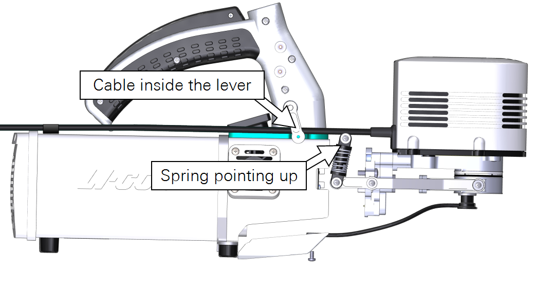
- Make them snug—turn each screw until it stops, and then about ¼ turn more. If you have a torque screwdriver, tighten them to 2.5 N·m (22 inch lbs).
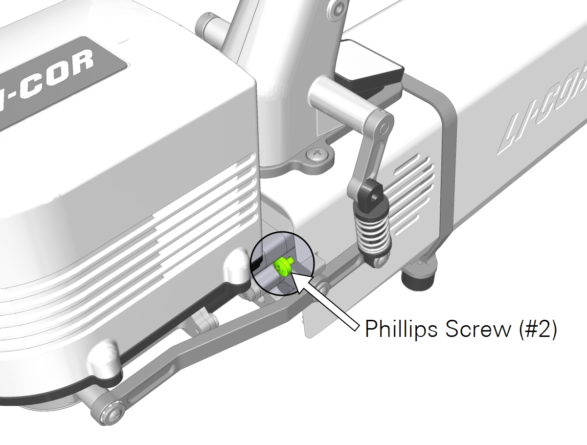
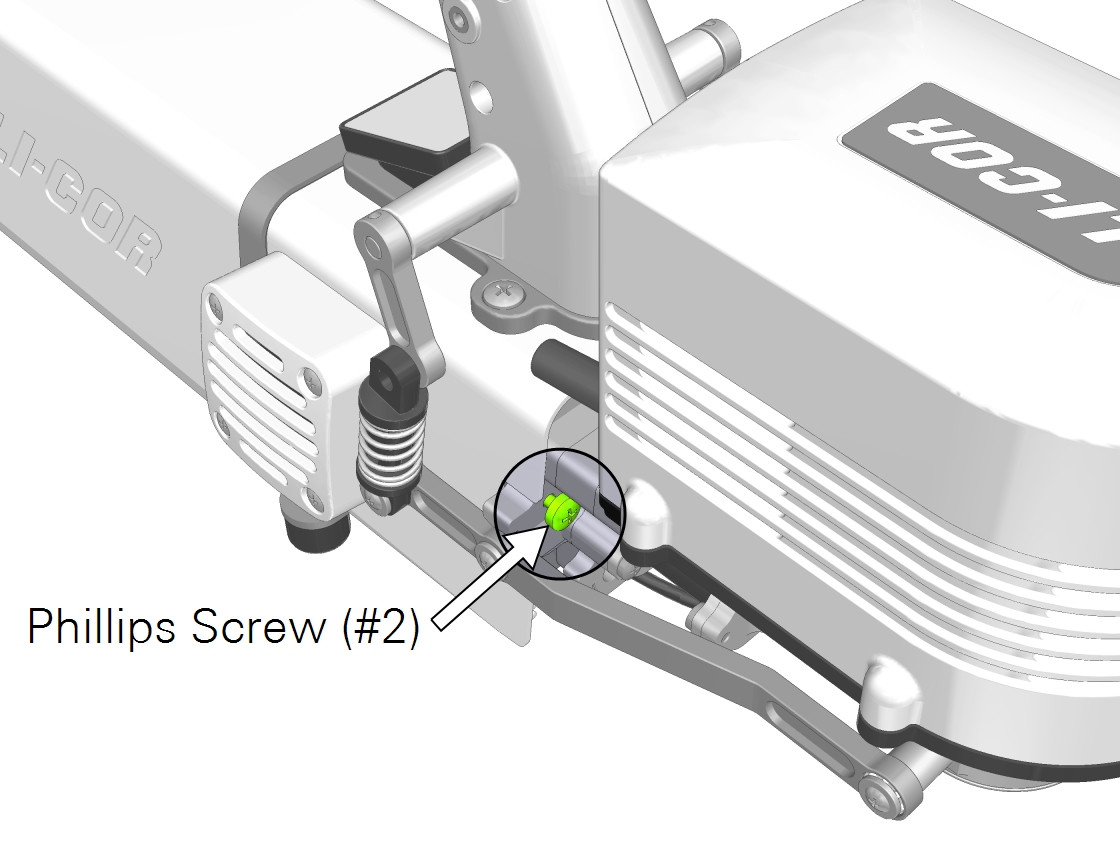
- Caution: You must use the captive chamber screws (part number 144‑15344) to install the chamber. Other screws will cause leaks and problems with the mixing fan, even if they seem to fit.
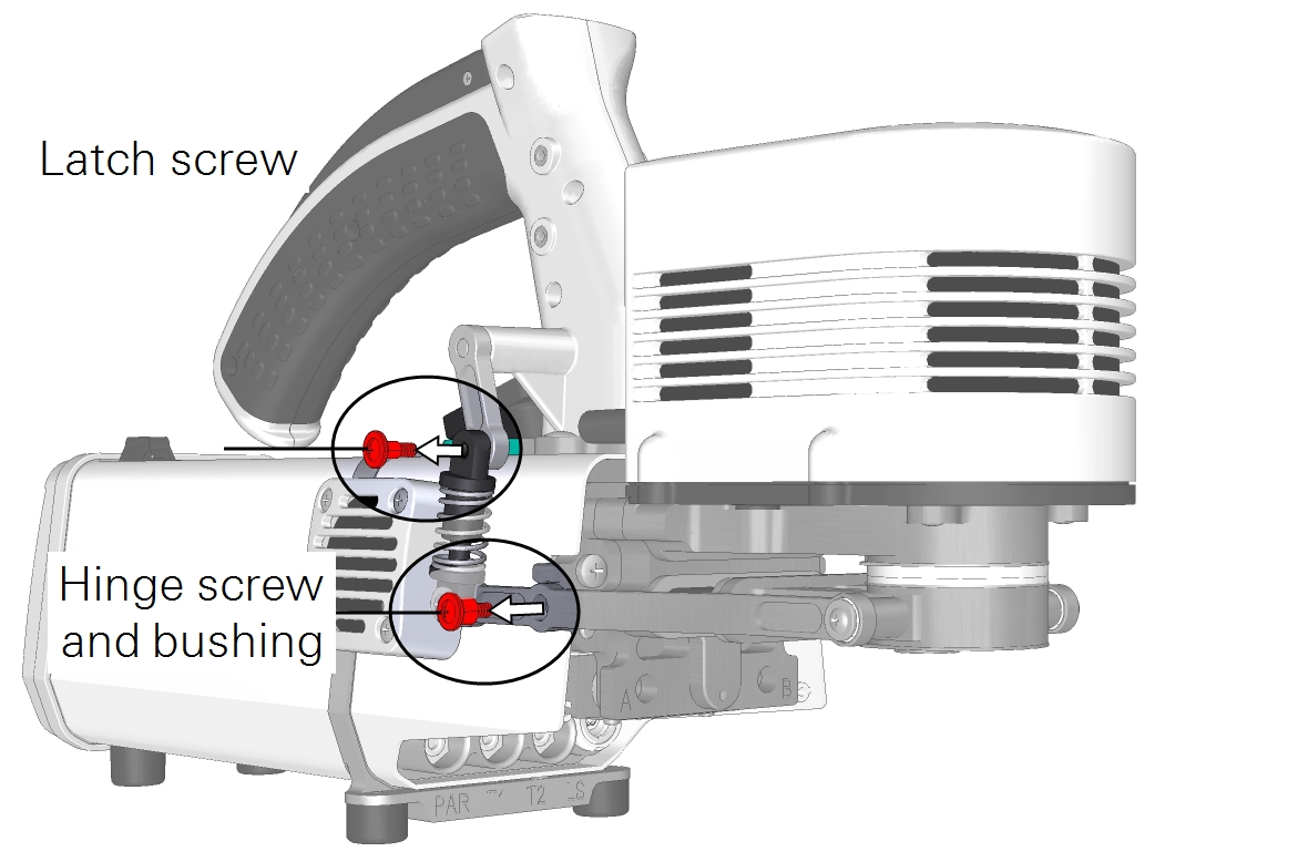
- Set aside the chamber latch screws.
- Do not lose them; but they are not needed for aquatic applications.
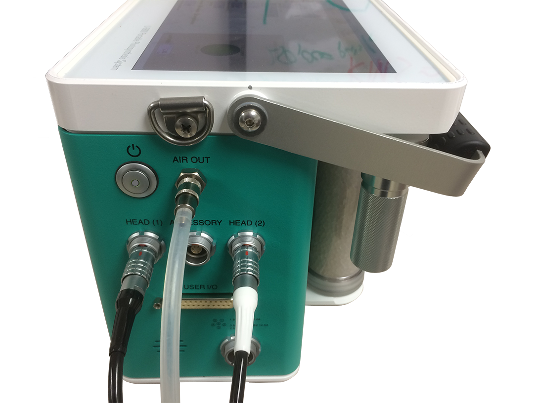
- Plug the fluorometer cable connector into the console.
- The fluorometer cable (with the white strain relief) and head cable can be plugged into either the Head (1) or Head (2) connector. The connectors are interchangeable.
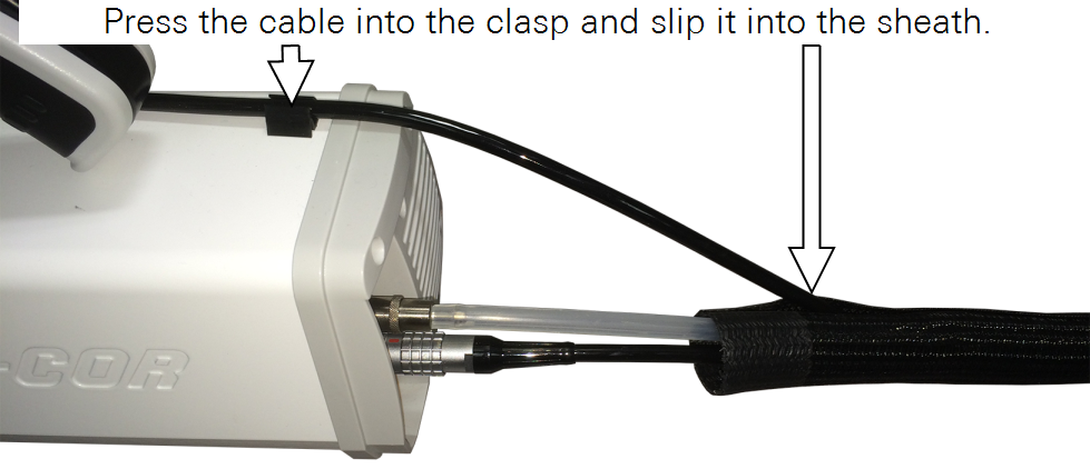
- Slip the cable into the head cable bundle and press the cable into the clasp.
Preparing the fluorometer
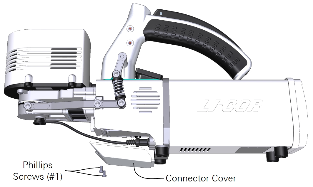
- Remove the connector cover from the bottom of the head.
- Remove the leaf temperature thermocouple from the chamber and unplug it. Keep it close by for re-installation later.
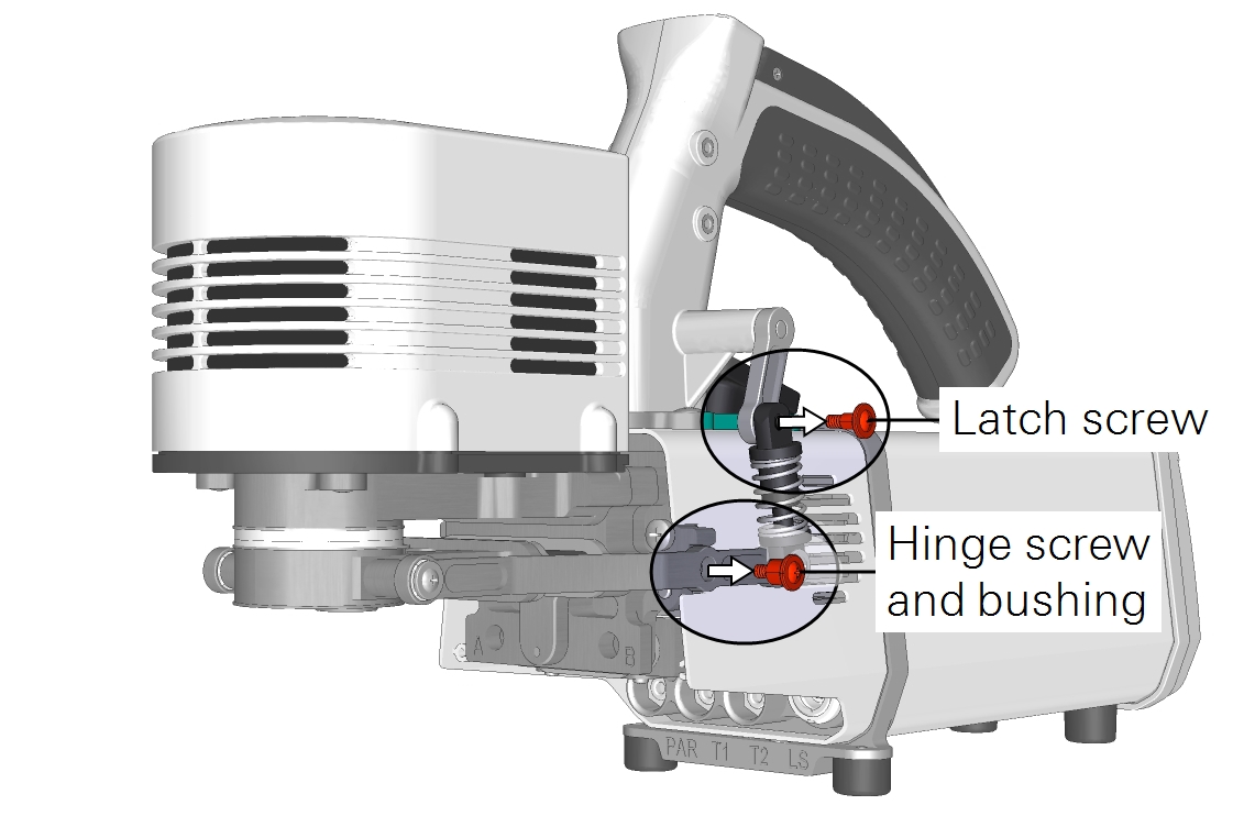
- Remove the lower half of the fluorometer chamber.
- Begin by removing the left and right chamber latch screws, hinge screws, and black plastic bushings (part number 6568-356). Put the hardware away for safekeeping.
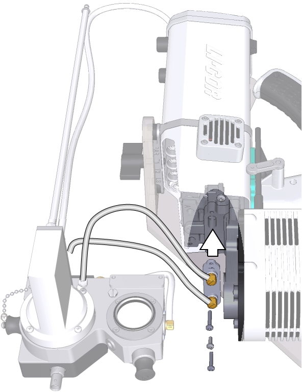
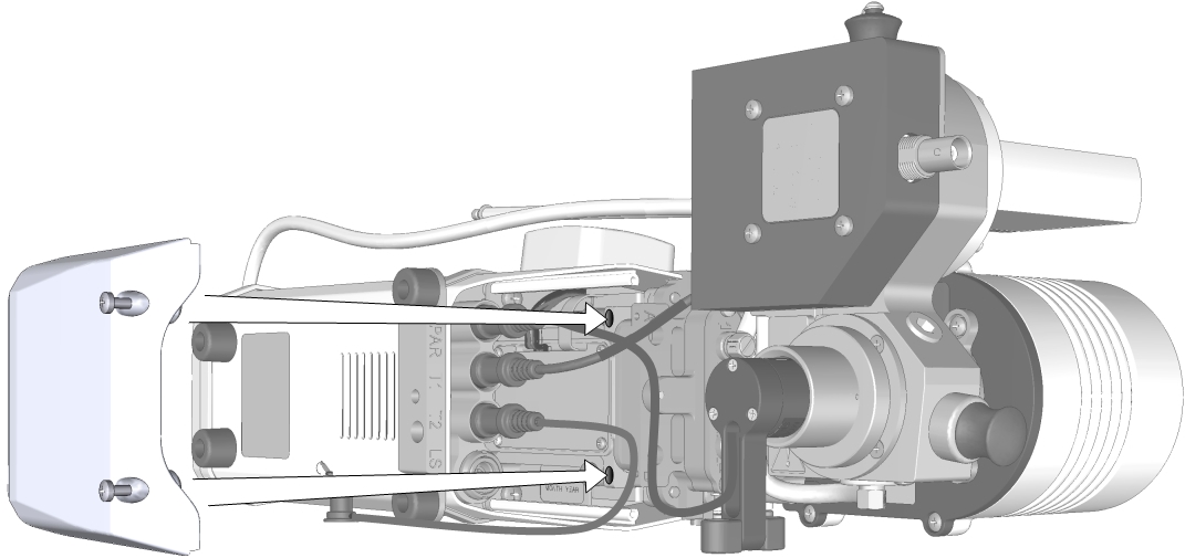
- Remove the three screws (two long and one short) that secure the flexible ducts to the head. Keep the screws close by for reassembly.
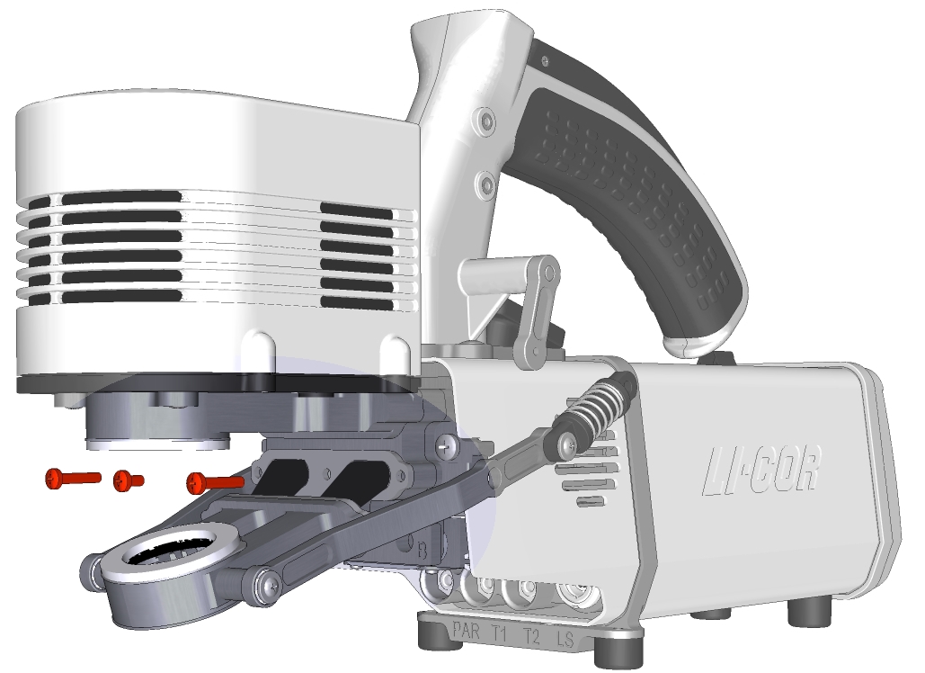
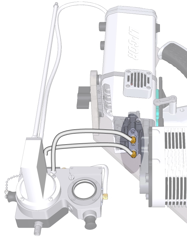
- The lower part of the chamber is now free of the head. Set it aside for safekeeping.
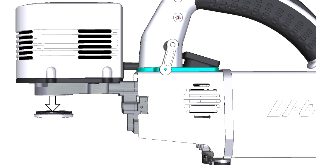
- Remove the aperture from the upper part of the fluorometer and set it aside for safekeeping.
Now you are ready to begin installing the aquatic chamber.
Installing the aquatic chamber
Handle the chamber carefully. Avoid touching the windows and be sure they are clean before connecting to the fluorometer.
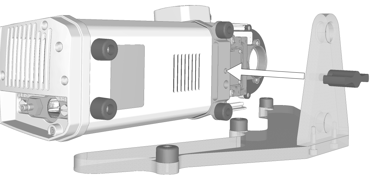
- Attach the aquatic chamber stand to the head.
- When the aquatic chamber is used to measure aquatic samples, the proper orientation of the head is on its side.
- Seat two O-rings (192-18247) in the manifold.
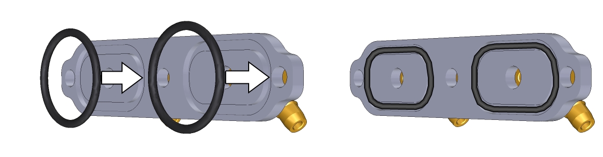
- Install the manifold onto the head using the two long and one short screw removed earlier. Be sure that the O-rings are in place. Tighten the screws snugly.
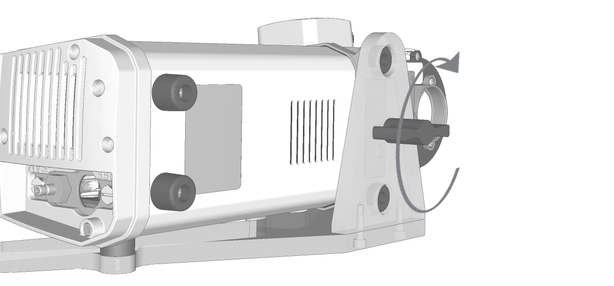
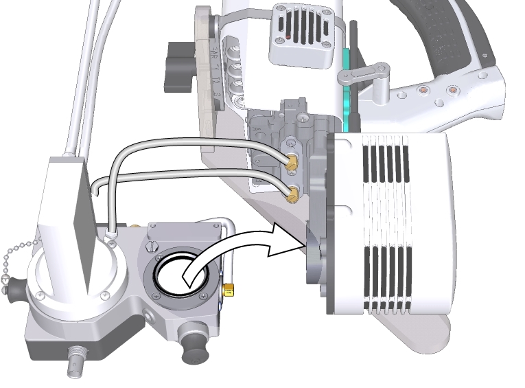
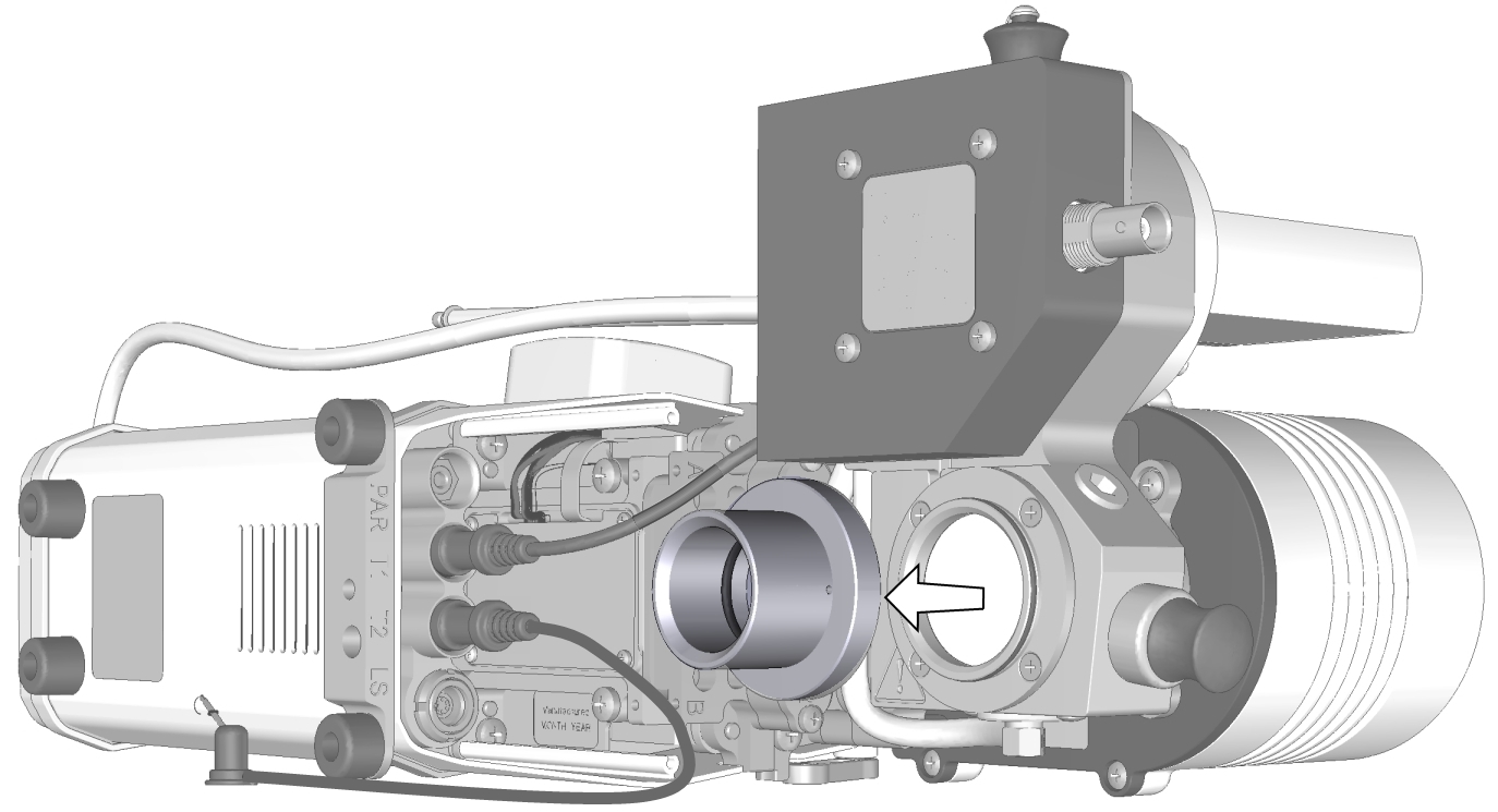
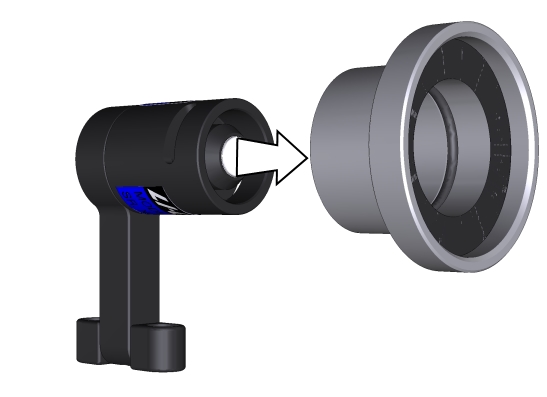
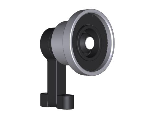
- Rotate the chamber into place. Insert the aquatic chamber aperture into the fluorometer optical opening. Ensure it is seated fully.
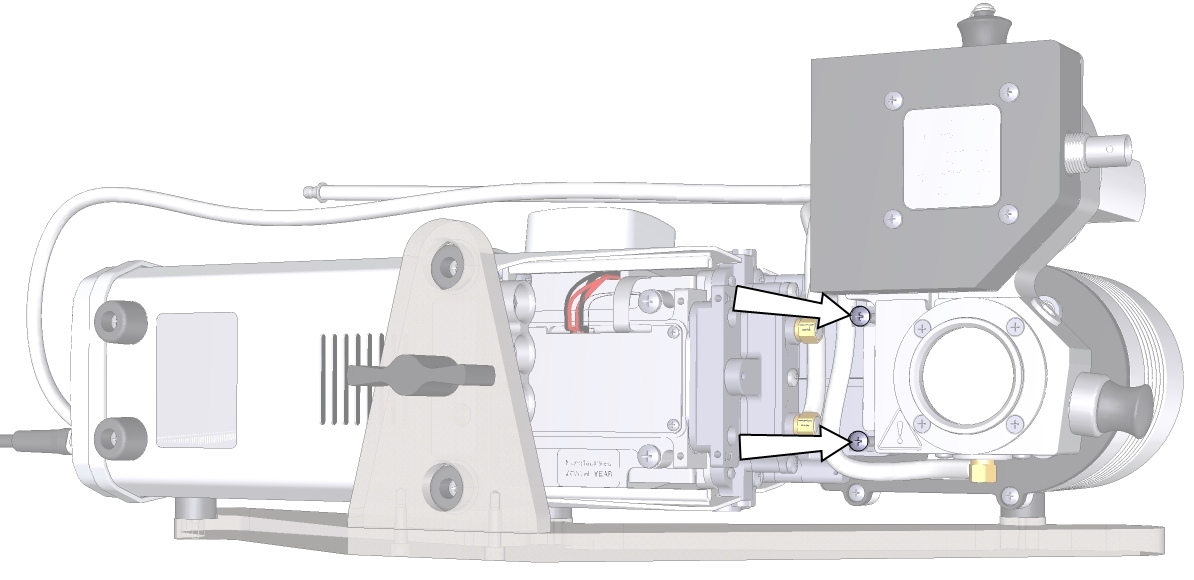
- Secure the aquatic chamber with two captive screws (145-19960). Early chambers used non-captive screws from the spares kit (150-14430).
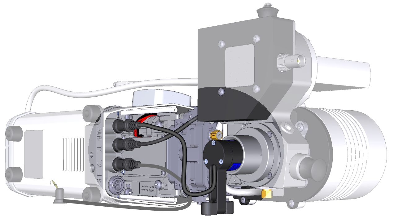
- Plug the aquatic chamber temperature cable into the connector labeled T1 and connect the thermocouple to T2 to measure ambient air temperature for additional protection from condensation.
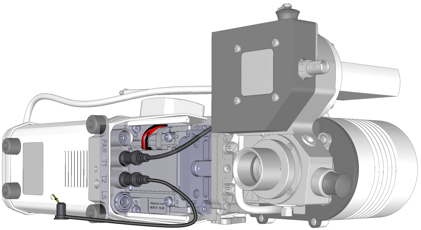
- Install the light sensor and connect its cable.
- Remove the light sensor aperture from the chamber.
- Press the sensor into the aperture until the diffuser is even with the black surface. It fits tightly.
- Reinstall the light sensor aperture on the chamber. Connect the cable to the connector labeled PAR.
- Attach the connecter cover.
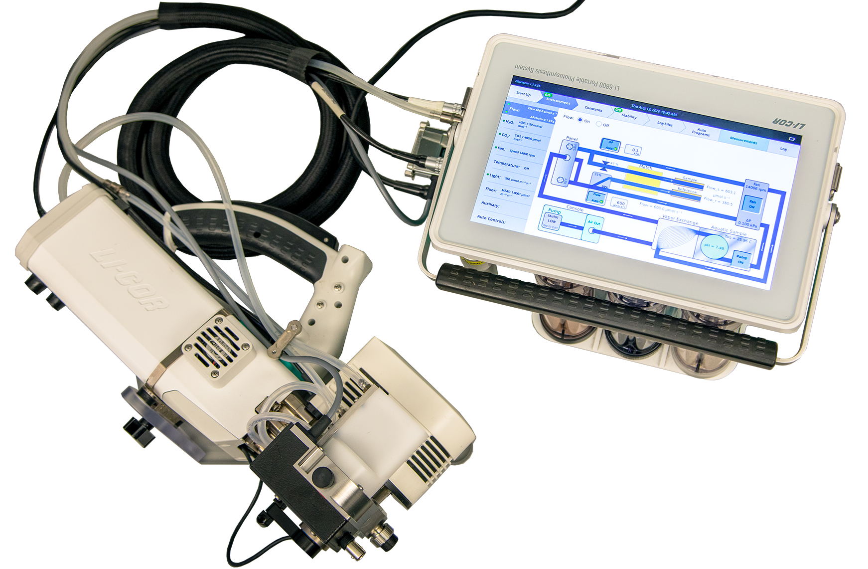
- Connect tubes and cables between the head and console.
- The head cable connects the console (either HEAD (1) or HEAD (2)) to the head. The fluorometer cable connects to the vacant HEAD (1) or HEAD (2) terminal. The DB-25 connector plugs into USER I/O. The tube from the H connector on the equilibrator connects to the head; the tube from the C connector on the equilibrator connects to the console tube.
- Tuck the tubes under the latch arm to prevent them from sitting on top of the thermoelectric cooler fan. This reduces the risk of a condensation point in the tube, which can happen if the sample temperature is other than ambient. Slip the cables into the sheath.
- Power on the instrument.
- After the instrument starts up, check the firmware version and update it if needed. Firmware version 1.5 or newer is required for the aquatic chamber. Download it from licor.com/li-6800-software. Update the instrument — be sure to update the fluorometer, head, and console.
Caution: Do not connect or disconnect the head cable while the instrument is powered on. Doing can cause damage to the internal circuitry, requiring repairs at the factory. Save money (and your reputation) by being sure to power off the console when installing or removing the head cable.
Entering the LI-190R calibration multiplier
- Power on the LI-6800 and go to Environment > Light > Ambient.
- You're interested in the settings under Meas: Qamb_out. Tap Unlock.
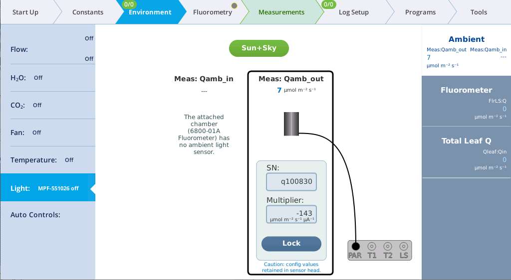
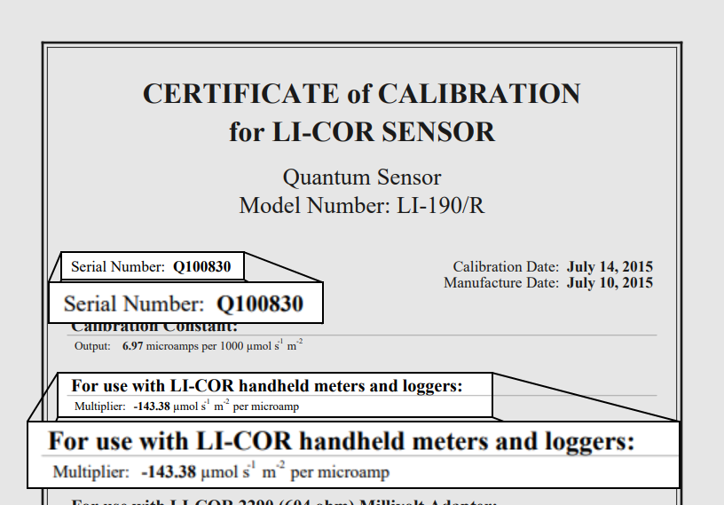
- Enter the serial number and multiplier for the LI-190R.
- The LI-190R calibration certificate is included with the instrument's documents. You can also retrieve it from licor.com/support/home.html. The unique multiplier for the light sensor is on the calibration sheet under For use with LI-COR handheld meters and loggers. It will be a negative number (probably different from the value in the example below).
- Lock the setting when you are done.
If you have followed the assembly up to this point, you can take a full tour of the interface starting with Preparations and verification. If you are familiar with the LI-6800 but new to the aquatic chamber, start with Aquatic chamber software controls. If you are ready to start a measurement, proceed to Preparing for measurements.