
Flow
The Environment > Flow screen shows—and lets you interact with—the flow control system.
Chamber options
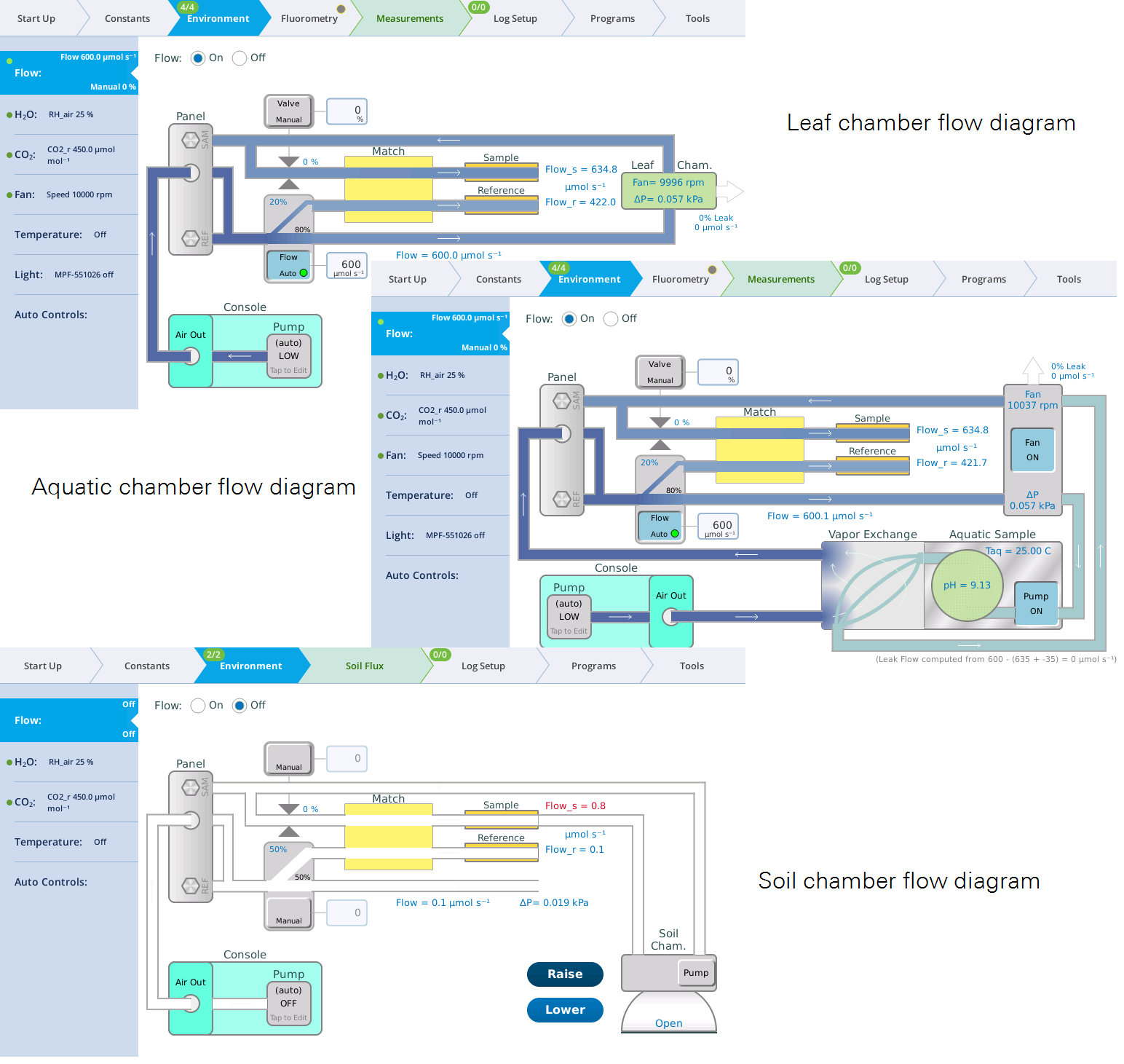
The form of the Flow screen is different depending on which chamber is attached. In this section we describe general options. For leaf-level and aquatic chamber gas exchange measurements follow the tours below and then see the respective sections for more details.
- Leaf chamber Flow options, including the fluorometer in the leaf configuration, are described in Leaf chamber software controls.
- Aquatic chamber Flow options are described in Aquatic chamber software controls.
- Soil chamber Flow options are described in Soil chamber software controls.
Pump speed and flow partition
Air flow originates from the console pump, which has settings of Auto, High, Medium, Low, Minimum, and Off. The Auto setting automatically selects the proper pump speed based on the requested flow rate. The flow splitter divides the flow coming into the sensor head into two paths: one path goes to the leaf chamber and sample gas analyzer, and the other path goes to the reference analyzer.

Leak rate
The flow tab shows a real-time estimate of the leak rate from the leaf chamber. This value is logged in a variable group called Leak.
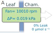
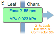
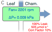
With the original 6800-01 and 6800-12 chambers (before the newer 'A' design), a leak correction calculated from the leak rate and fan speed is applied to the assimilation calculation. When a leak gets large enough that the correction becomes more than 2% at very low fan speeds, the fan control diagram will clearly show you the relationship between fan speed and the leak correction factor, allowing you to select a fan speed that keeps the correction factor at a negligible level. If, for some reason, you have large leaks and you need a low fan speed, then you will clearly see the degree to which your results will depend on the leak correction. For the newer 6800-01A and 6800-12A chambers, leaks should not affect measurements. The leak rate is a diagnostic and not critical as long as there is enough flow to flush the sample IRGA (>100 μmol s-1).
The mixing fan controller provides guidance for selecting a suitable fan speed. See Fan for details.
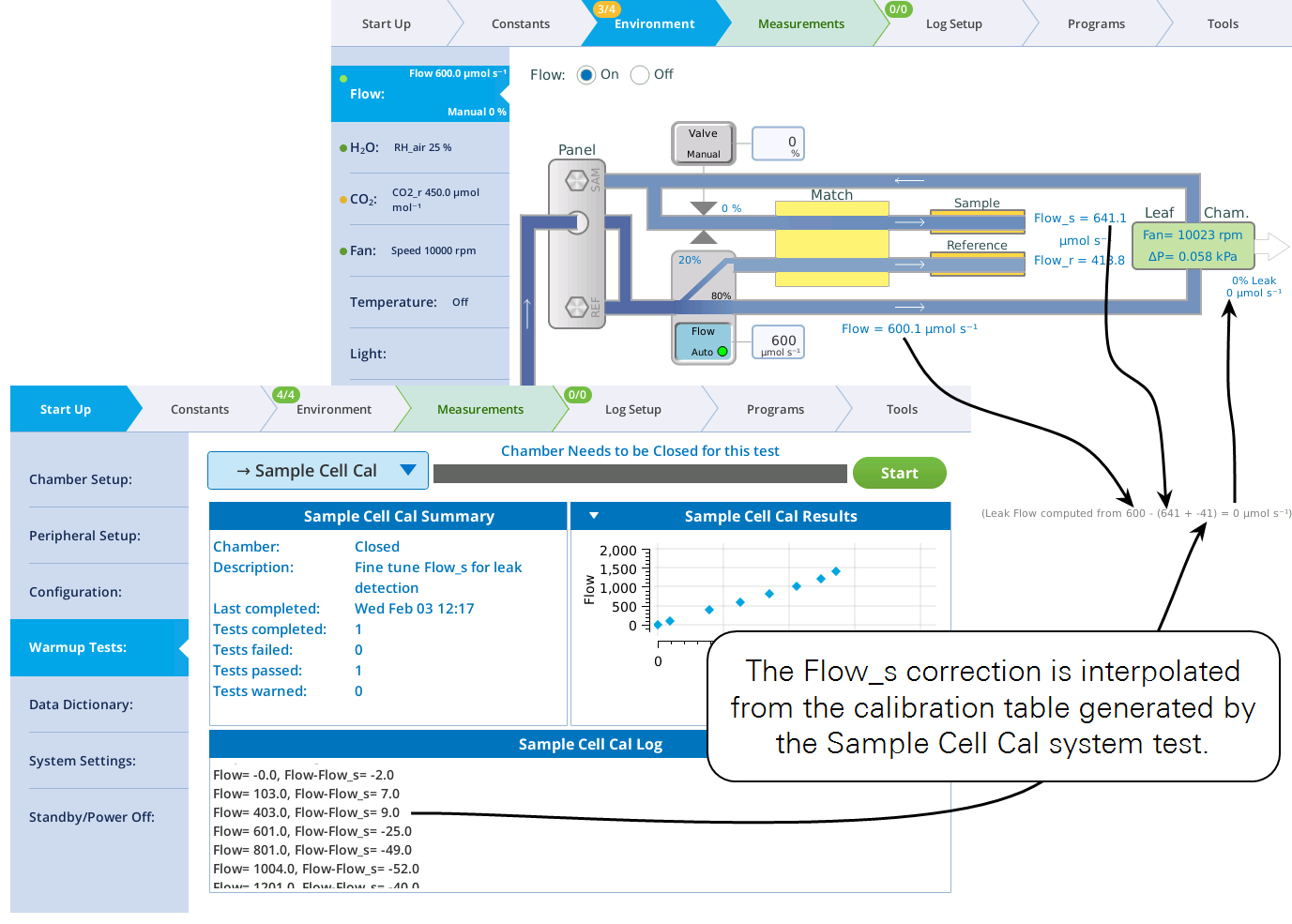
The diagram includes an explanatory footnote about how the leak flow value is computed.
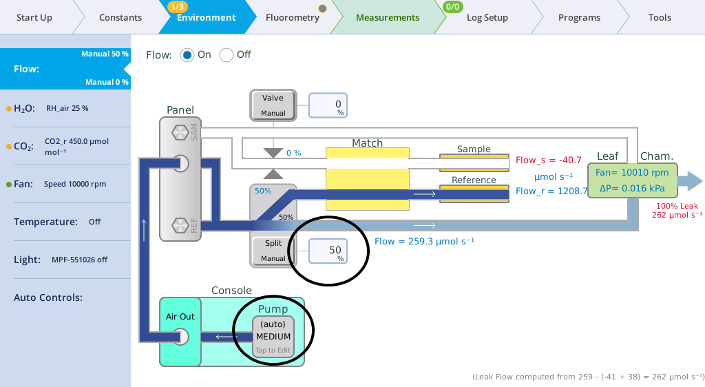
Manual flow control
- Start with the chamber open.
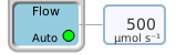
- Set Flow to On.
- Tap the button below Pump and set the pump speed to Low.
- Set the Flow rate to the chamber.
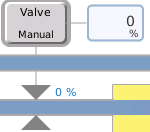
- For manual control, you want to set flow as a "flow control valve" percent and enter a value of 50%. Be sure the overpressure is off or set to 0 kPa.
-
- Close the chamber and notice what happens.
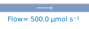
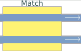
- Paths with airflow are now blue—a shade that is proportional to flow rate. In the example above, the flow meter show how much flow is going to the leaf chamber and sample IRGA. The remainder is going to the reference IRGA. These values will be slightly different for your instrument.
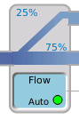
- Tap the flow split graphic and enter a different setpoint such as 80%.
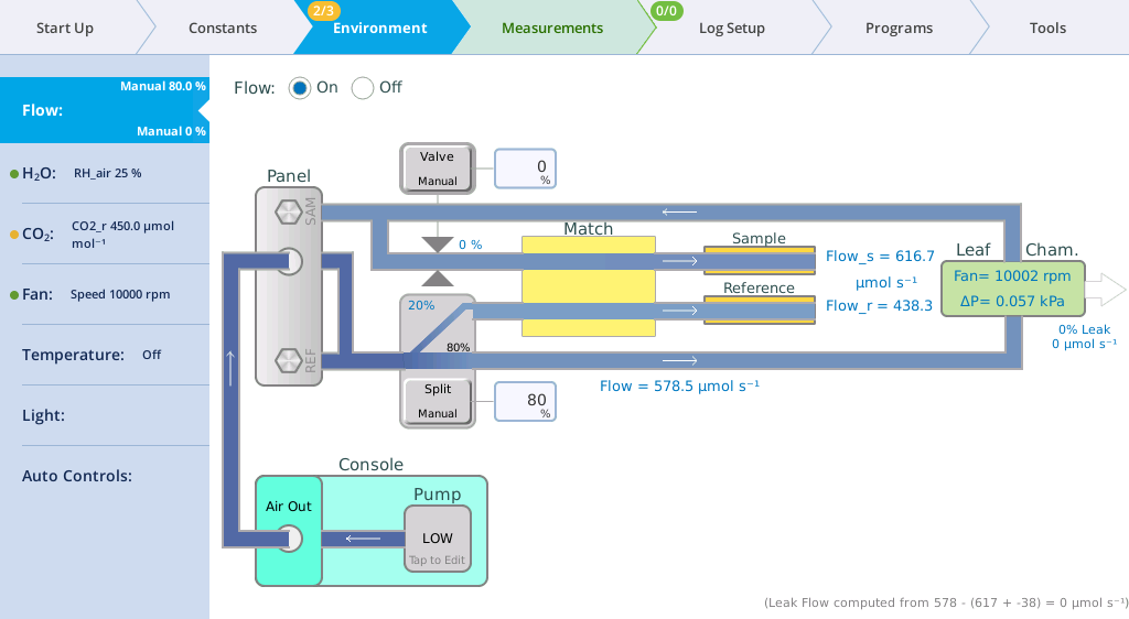
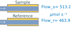
- Try some other values to see how the Flow_r and Flow_s values change with different settings.
Automatic flow control
In normal operation, you don't need to set the flow splitter manually. You can let the instrument do it based on a target value you enter.
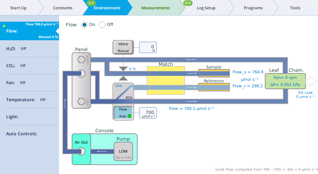
- Set the Pump to Auto.
- Close the chamber and enter a target flow of 700 µmol s‑1.
- The flow controller will very quickly bring the flow to the target value. Also, you have about 760 µmol s-1 left over for the reference cell (this number will be different for your instrument). The dot on the Flow tab turns green and the 0/1 on the Environment tab becomes 1/1, indicating that the setpoint has been achieved.
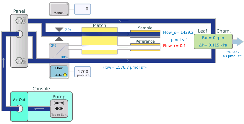
- Set the target very high, such as 1700 µmol s-1.
- Notice you have very little flow left over for the reference cell, and its flow dropped to a value that is too low (indicated by Flow_r Low warning message and the white reference flow path).
Balanced flow
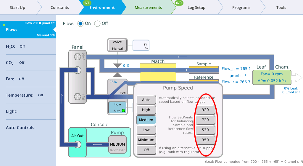
Having sample and reference flow rates balanced can be advantageous for eliminating potential errors, and it is now easier to achieve. For every pump speed, there is one flow rate that will match sample and reference flows (to within 5 mol s-1). To quickly get to that flow rate, simply tap the Pump button on the Flow control page to bring up the Pump Speed dialog (Figure 3‑11). Tap one of the four flow rate possibilities presented on the right side.
There are two Background Programs that deal with balanced flow:
- When you tap one of the balanced flow setpoint buttons, a BP (
/home/utility/apps/system/balance_flow.py) is launched (no opening dialog) a few seconds later to check on the result, and fine-tune the flow if needed. That fine-tuning will automatically update the balanced flow setpoint for that pump speed. (Note: the chamber must be closed, of course, for the flows to match. If the chamber is open, then the BP won't attempt to adjust the flow rate.) - The BP
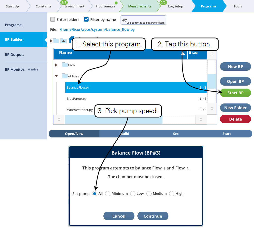
/home/utility/apps/utilities/Balance_Flow.pyhas an opening dialog that lets you pick what pump speed to use (Figure 3‑12), then balances the flow for that speed. (Cycling through all four pump speeds is also an option.) Running this program also updates the balanced flow setpoints shown in Figure 3‑11.
There is also a hidden shortcut: If you tap the flow rate setpoint edit box (the one you normally use to enter a new flow rate), and enter an E instead of a value, the balance_flow.py BP will be launched. If the pump is in Auto mode, it will change to the non-automatic version of its current speed, and the flows will be balanced.
Chamber overpressure
If you are measuring irregular leaves and the chamber does not seal very well, you can increase this setting to force leaks out and minimize inward diffusion of ambient air.
- Set up the instrument for automatic flow control at 500 µmol s-1, and close the chamber.
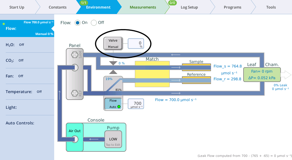
- The button will display either Valve Manual or ΔP Auto, depending on the setting.
- Tap the button to change the setting. Tap the field to enter a setpoint.
- For Chamber overpressure, enter 0.1 kPa. The instrument limits pressure to 0.2 kPa to prevent damage to itself.
- Change the setting back to 0 kPa after you are done
- Use 0% or 0 kPa for most measurements. If you use the chamber pressure option, a setpoint of 0.1 kPa is the maximum setting specified, although the instrument does allow you to enter setpoints up to 0.2 kPa.