Light
Under Environment > Light, you'll find 5 subtabs where you can configure light settings. You may observe that some tabs are missing, depending on which light source is connected. For example, if you have a fluorometer connected, the Head Light Source and Console Light Source tabs will be blank. The options described here apply to the 6800-01/A fluorometer, 6800-12/A small leaf chamber, and 6800-13 large leaf chamber.
Measuring ambient light
With the 6800-12/A small leaf chamber and 6800-13 large leaf chamber, you have the option to use ambient light to illuminate a leaf. Light can be the sun, office lights, growth chamber light, or whatever light is driving photosynthesis in the sample plant. If your instrument has a light source installed, remove it so the chamber top is open to ambient light. Skip this exercise if you only have the fluorometer.
- With the instrument powered on, observe the values of Meas: Qamb_in and Qamb_out.
- These are the measured ambient light in and out of the chamber, respectively.
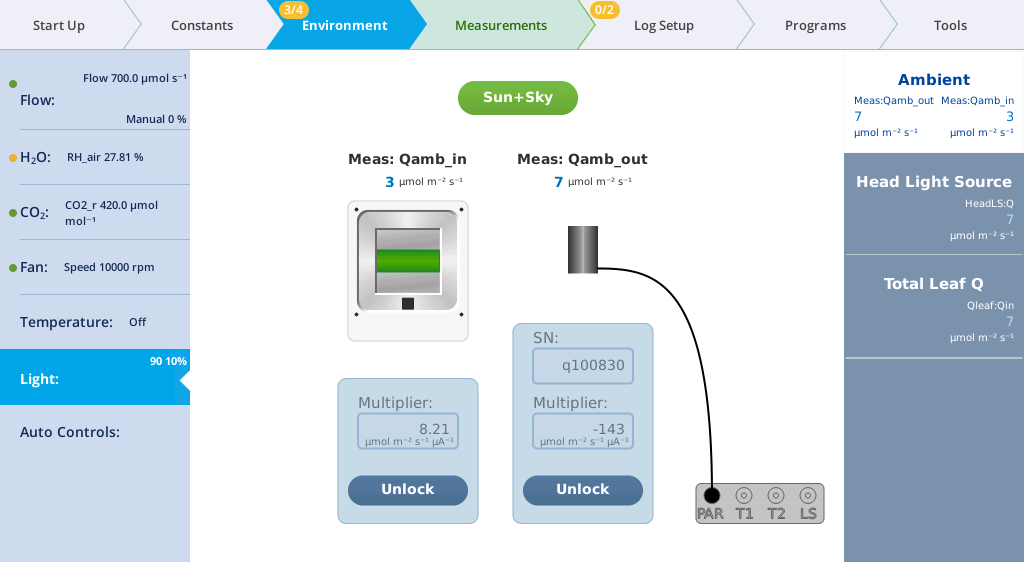
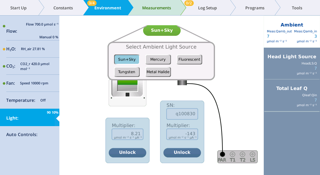
- Select a light source.
- Tap the button (labeled Sun + Sky in the example), then choose the option that best represents your lighting conditions.
- Specifying the correct ambient light source is necessary for using energy balance (for calculating Tleaf, for example) or to estimate Qabs. The absorption coefficient (α, how much of the incident radiation is being absorbed by the leaf) is directly related to the wavelengths output by the light source. A list of absorption coefficients and their values can be found under Constants > Light.
- Place your hand over the clear chamber top to block the internal light sensor.
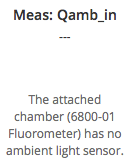
- Observe the value of Meas: Qamb_in on the display. It will drop to near 0 µmol m‑2 s‑1 when the chamber is covered. The chambers with ambient light sensors are the 6800-12, 6800-12A, and 6800-13. If the attached chamber does not have a built-in light sensor, this box will be empty.
- Now place your hand over the LI-190R sensor.
- Observe the value of Meas: Qamb_out on the display. It will drop to near 0 µmol m‑2 s‑1 when the sensor is covered. You may also see Meas: Qamb_in drop if your hand shades the chamber.
The Fluorometer tab
Fluorometer options are described in Fluorometry > Settings screens. If you have configured the fluorometer as Light Source Only, the general light source options apply.
The Head Light Source tab
The Environment > Light > Head Light Source tab is where you configure the light source that is attached to the LS connector underneath the sensor head. These settings are applicable to the small (3×3 cm) light source. The large (6×6 cm) light source has similar settings, with additional controls for the additional LEDs.
The Console Light Source tab has the same controls as Head Light Source. It is to configure a light source connected to the ACCESSORY connector on the console (see Using two light sources simultaneously.
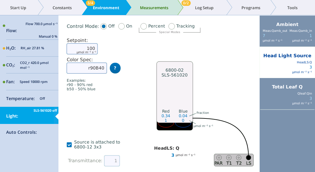
You can specify the Control Mode for light sources that are connected to the head or console connector. The options are:
- Off: Disables the light source LEDs.
- On: Lets you enter a Setpoint for the quantity of photons (Q) in µmol m-2 s-1.
- Percent: Controls the light source as a percentage of maximum drive voltage to the LEDs.
- Tracking (3×3 and 6×6 cm light sources only): Generally this is set to track Qamb_out, as measured by the LI-190R. When tracking is selected, the Setpoint field will continually come from the external quantum sensor (editing is disabled). To track ambient light with the fluorometer, see Control light by tracking ambient (fluorometer).
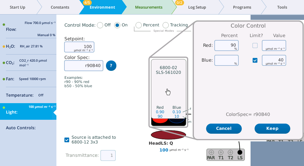
In any Control Mode, you can set the Color Spec using a simple shorthand, which is described in Color spec.
Transmittance: A transmittance factor to account for any losses between the lamp window and the leaf.
Light source exercises
In this exercise, you'll need a light source to be installed. We describe the 3×3 cm light source. The 6×6 cm light source is configured similarly, with more options for the green and white light. For this exercise, open the chamber so you can see the light that shines out of it. Remember, never look directly into the light source.
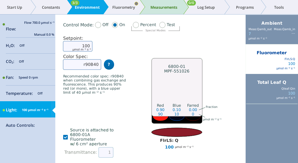
Control light on a setpoint
With the Setpoint control, you can set the light intensity (Setpoint; µmol m‑2 s‑1) and adjust the proportion of red and blue (Color spec). The variables Red and Blue indicate the fraction of each color.
- Under Environment > Light > Head Light Source, select On.

- For the Setpoint, enter 100 µmol m‑2 s‑1.
- Observe the light that shines out of the chamber.
- If it is not already set, enter r90B40 for the Color Spec.
- The default setting is r90B40, providing 90% red with a maximum blue light of 40 μmol m-2 s-1.
- The % red will increase after 40 μmol of blue light is reached. This is a common ratio for photosynthesis measurements.
- Tap the light source graphic to open the Color Control window.
- Tap the red and blue labels on the light source diagram to open a window that allows you to easily set the color spec through the interface. See Color spec for more details.
-
Control light on a percent
With the Percent control, you can set the red and blue as a percentage of power available. Maximum irradiance is achieved when you enter 100 for both red or blue.
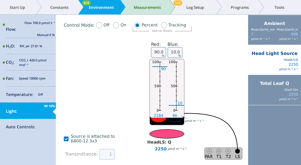
Observe the relationship between the percentages entered and the measured light.
Powering the red LEDs at 90% and the blue LEDs at 10% gives a Head LS: Q of about 2204 μmol m-2 s-1 in this example. The exact values for your instrument will be different.
Control light by tracking ambient (3×3 or 6×6 cm light sources)
When using an 3×3 cm or 6×6 cm light source, the Tracking control sets the light source brightness to track ambient light, as measured by the LI-190R quantum sensor. With the 3×3 cm light source, you can control red and blue. A typical Red:Blue ratio is 9:1, which is established by a Color Spec of r90. The 6×6 cm light source and fluorometer provide more color controls.
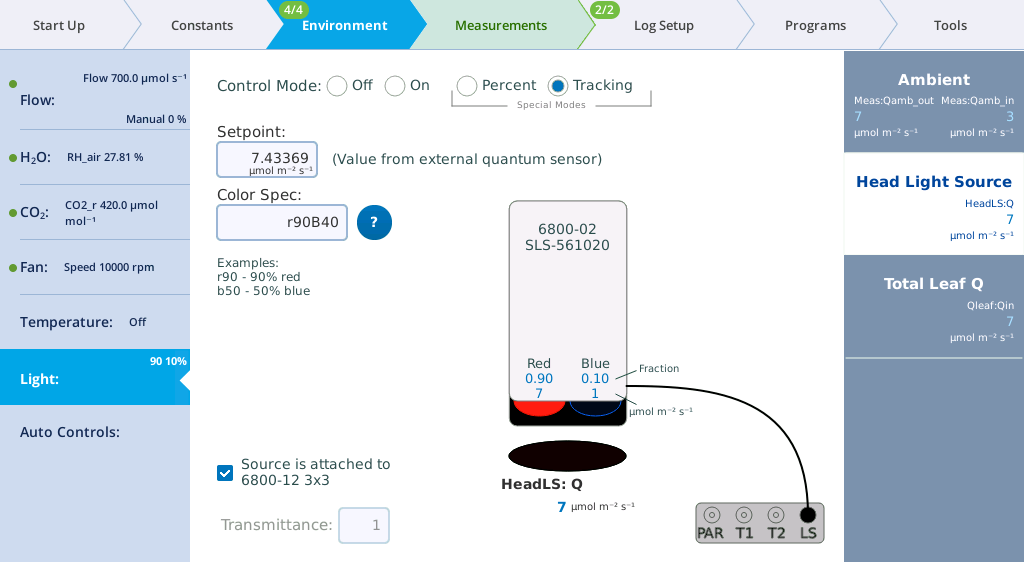
- Observe the values for Setpoint and HeadLS: Q.
- The Setpoint value is driven to measured Qamb_out. In this example it is 7.16 µmol m‑2 s‑1 from the fluorescent lights in the LI-COR office.
- Place your hand over the LI-190R to block the light.
- Observe Head LS: Q. It should quickly drop to near 0 µmol m‑2 s‑1.
- Lift your hand off of the light sensor and watch the Setpoint and Head LS: Q return to the previous value.
Control light by tracking ambient (fluorometer)
With the fluorometer, tracking ambient light is configured with an Auto Control. To track ambient, go to Environment > Auto Controls, select a parameter (1 to 6), and set the Target to control Env Light Controls > Qin. Set the Function F(t) to tracking. Set Track this variable to Qamb_out. Check the AutoRepeat box, and then tap Start. When tracking ambient with this configuration, the Environment > Light tab will indicate that these parameters are under the control of the Auto Control.
Transmittance factors
Transmittance factors allow you to think of light source setpoint targets as what the leaf is receiving, which may or may not be what the light source is actually producing. The fluorometer and 3×3 cm light source are calibrated with chamber tops in place, so their transmittance factors are 1.0. This is not necessarily true when apertures are used. The 6×6 cm light source is calibrated without any chamber top, since there are multiple chambers it fits on. It has transmittance factors for each chamber type.
When you connect a chamber (or specify a chamber ID under Start Up > Chamber Setup) the LI-6800 will automatically choose the appropriate transmittance factor for that chamber. If you suspect that the transmittance factor is not correct, you can verify it from Table 3‑3.
If you have a custom method of illuminating a chamber (for example, using a 6×6, 4 color light source (6800-03) suspended above a 3×3 chamber), you will need to measure the transmittance factor for that configuration. A simple way to estimate this is to set the light source to 1000 mol m-2 s-1, then compare the reading of a quantum sensor that is pressed against the face of the light source (e.g., 1082 mol m-2 s-1) with the reading beneath the top of the chamber at leaf level (e.g., 774 mol m-2 s-1). The transmittance is the ratio: 774/1082 = 0.72. Once that transmittance is entered, setting the light source to 500 mol m-2 s-1, will cause it to actually put out 500/0.72 = 694 at its face, in order to achieve 500 at the leaf surface.
Light source factory calibration settings
The Show Cal button gives access to light source factory default settings and calibration data. The information in this tab is for diagnostic purposes. Do not change it unless in consultation with technical support.
Total leaf Q
The fifth tab, Total Leaf Q, is where you specify which light source(s) contribute to the light on the leaf. The Customize button allows you to weight each light source's contribution to the leaf, to accommodate nearly any scenario. For example, a 3×3 cm or 6×6 cm chamber with a light source mounted on the top and bottom will be configured this way. You can Use Default values for the light sources, or Customize them by entering a multiplier.
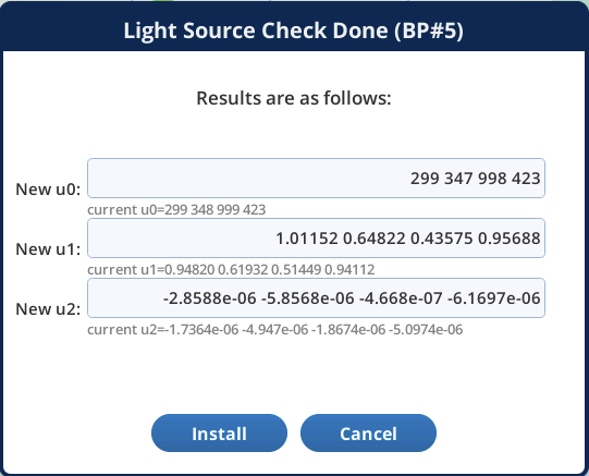
Light source test program
The Test button on light source control screens that launches a background program that checks some of the calibration coefficients (u1; u2; u3). This test is only available to light sources that attach to the head or console (not the MPF fluorometer).
The values in u0 are found by determining each color control's on/off threshold. The other values (u1; u2) relate control setting to color output, and are important for determining color mix to achieve the specified value. These values should be fairly stable with time, but are easily checked. The test that is launched (/home/licor/apps/tech/LightSourceCal.py) is best done with the light source in the dark; if the light source is attached to a chamber, then clamping the chamber onto something very unreflective (black felt, for example) is recommended.
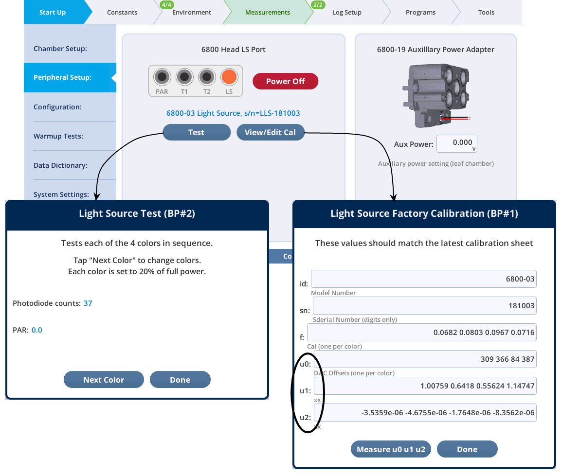
When it is done, another dialog is presented showing the results. Tapping Install will update the coefficients with those that were just calculated.