
The infrared gas analyzers will need periodic care to prevent calibration drift and ensure reliable performance. The frequency of maintenance will depend somewhat upon the use conditions and the carefulness of the operator.
Caution: Power off the instrument before following these procedures.
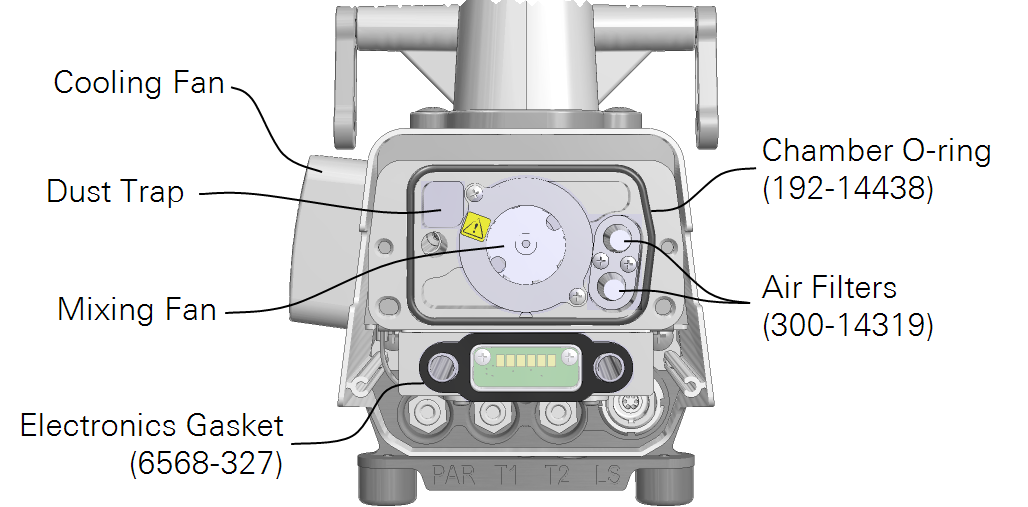
There are two small air filters in the head between the leaf chamber and the gas analyzer. These filters help prevent debris from entering the gas analyzer. You may need to clean or replace them periodically. There also is a dust trap that will collect dust.
- Remove the leaf chamber as described in Removing a chamber.
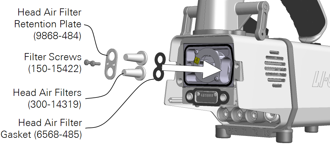
- The filters are held in place with two screws (M2; 6 mm long), a retention plate (part number 9868-484), and gasket (part number 6568-485).
- If the filters are clogged, replace them with new filters from the spares kit (part number 300-14319).
- Clean the internal surfaces around the fan, filters, ducts, and dust trap with a small swab from the spares kit.
- Install a chamber and perform the leak test.
Caution: Power off the instrument before following these procedures. Wear the anti-static wrist strap during this procedure. This will prevent static discharge.
There are two small plastic bottles in the analyzer housing that keep the detectors free of CO2 and water vapor. The bottles should last two or more years. Be sure that you have carefully considered every possible cause of an issue before concluding that the chemicals need to be replaced.
To change the sensor head soda lime and desiccant bottles:
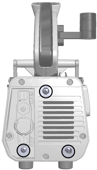
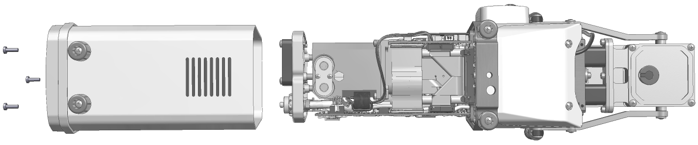
- Remove the shell from the head.
- The shell is secured with three Phillips screws. Remove the screws with the #1 screwdriver. Slide the shell off of the rear of the head as shown.
- Caution: Handle the head very carefully when the shell is off. Do not touch or bend the circuit boards.
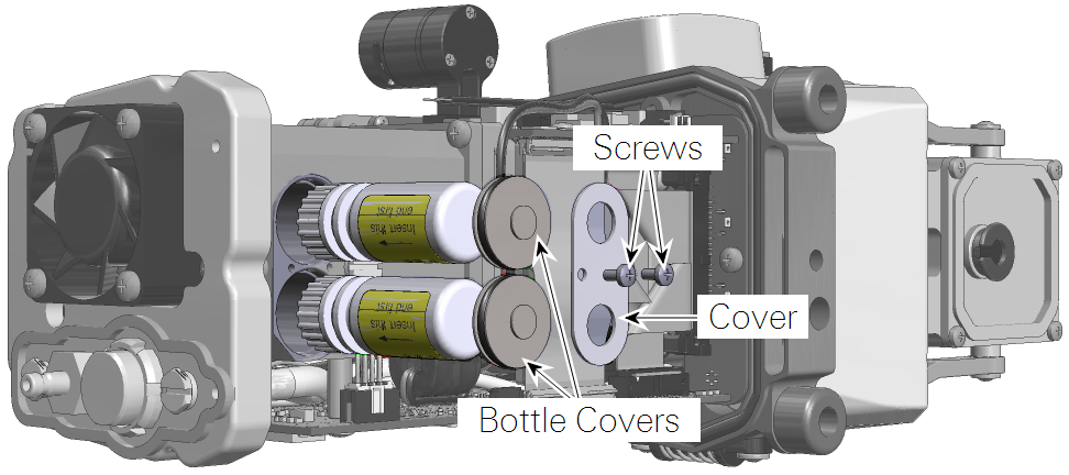
- Remove the bottle cover screws, cover, and bottle covers.
- Once the cover is removed, the bottles will slide out. You may need to grip them with your fingernails.
- Prepare the new bottles.
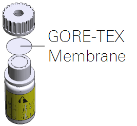
- If you have replacement bottles from LI-COR you should take the caps off of the removed bottles (the caps have a hole in the top) and put them onto the new bottles. So, the bottles that go into the head will have a hole in the cap. The GORE-TEX membrane should stay in the cap.
- Reassemble the head.
- The bottles go into the head with the caps toward the top of the sensor head. Reinstall the bottle covers, cover, and then tighten the screws snugly. Gently install the shell, and reinstall the three screws removed in step 1.
- When you install the shell, be sure that the full perimeter sits against the recessed gasket on the front of the bulkhead, and that it is not touching the bulkhead directly. Tighten the three screws to secure the shell.
Note: After replacing the bottles, let the instrument sit for a day before checking the zeros. The bottles will need this time to scrub CO2 and water vapor from the analyzer. You can speed this up by letting the instrument sit with the power on. If you do not wait, the zero will be incorrect.
The LI-6800 gas analyzers are open to the leaf chamber, but there are two filters that will prevent most debris from entering the gas analyzers. If the optical bench gets any debris in it you will need to access the gas analyzers and clean the optics. Do not open the optical bench unless you are certain that the optics are contaminated.
Caution: Power off the instrument before following these procedures.
- Remove the chamber as described in Removing a chamber.
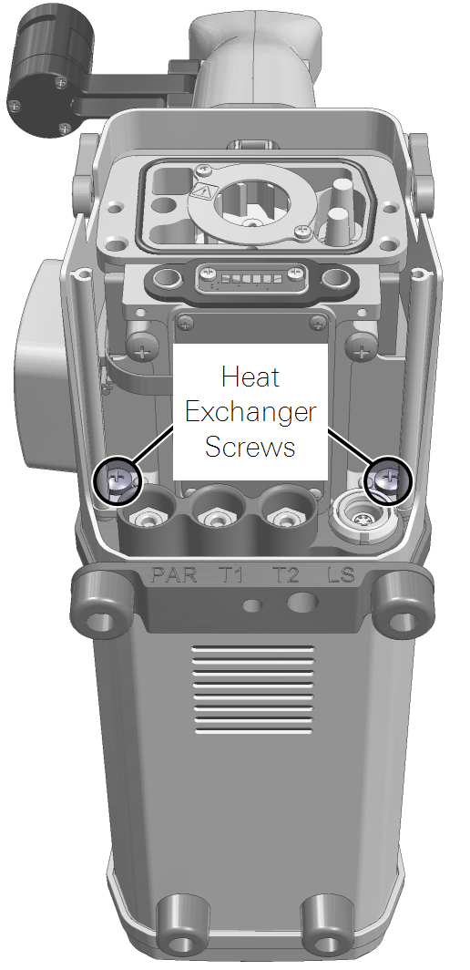
- Remove the heat exchanger assembly.
- The heat exchanger is secured with two screws—one above the PAR connector, and the other above the LS connector. The screws are captive. They only need to be loosened until they move freely.
- Set aside the heat exchanger and handle assembly.
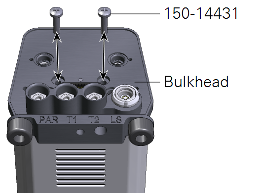
- Remove the bulkhead cover.
- The bulkhead cover is secured with two screws (part number 150-14431). Remove them.
- Gently flip over the bulkhead, exposing the gas analyzers.
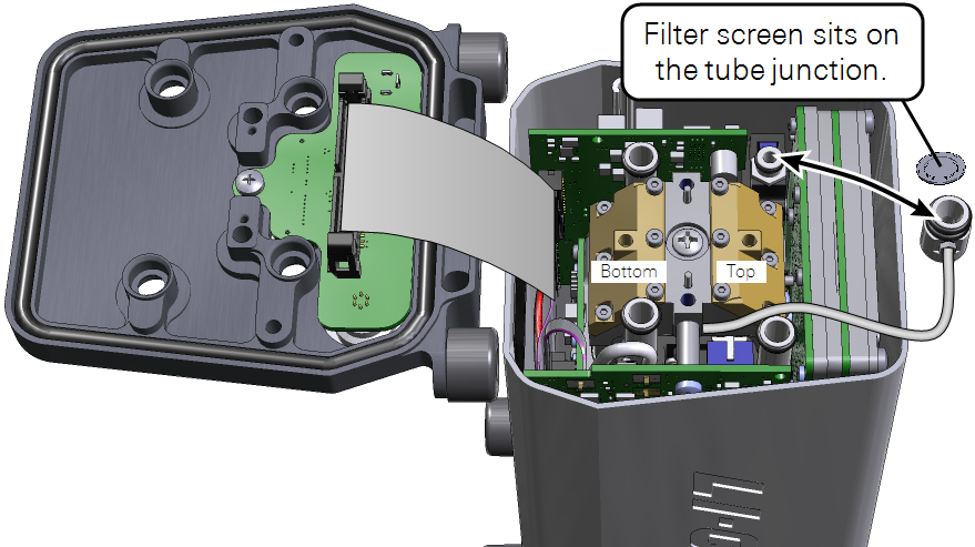
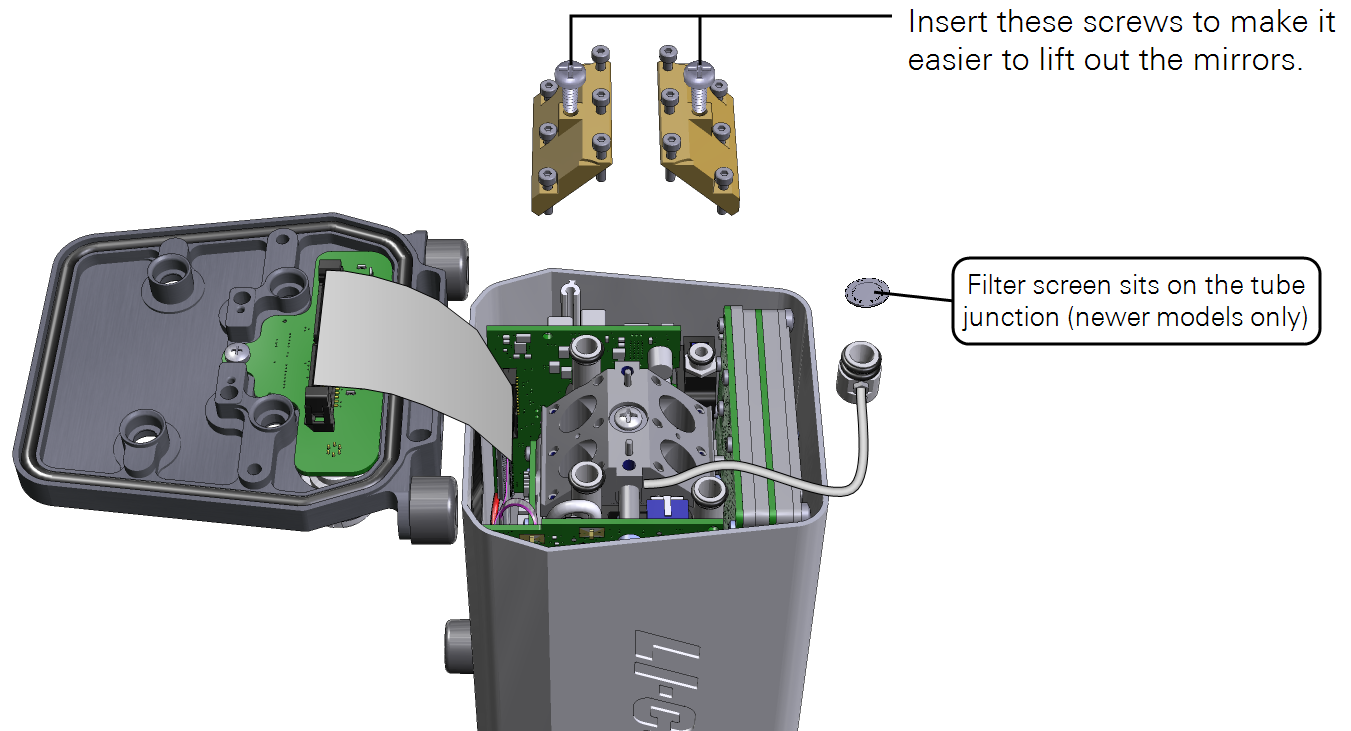
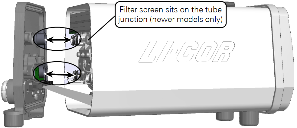
- You can leave the ribbon cable in place. Lift off the pressure tube and move it to the side. Newer models include a screen on the pressure tube.
- Mark the mirrors "Bottom" and "Top" with a permanent marker to help you remember which is which.
- If you get the mirrors mixed up, you'll probably have a calibration shift. Remember the two screws that held the bulkhead? Insert them (or part number 150-14431 from the spares kit) into the threaded holes in the mirrors. Hold onto these screws when lifting out the mirror.
- Completely loosen each of the six screws and lift out the mirror.
- Inspect the IRGA volumes and sapphire windows.
- If there is visible contamination, wipe them with the large swabs (part number 610-05315) from the spares kit to remove contamination. Blow out the IRGAs with canned or compressed air.
- Wipe the mirrors with a soft lint-free cloth.
- Use the soft cotton glove that is included in the spares kit.
- Caution: Do not use swabs on the mirrors. Swabs can damage the delicate surface of the mirrors.
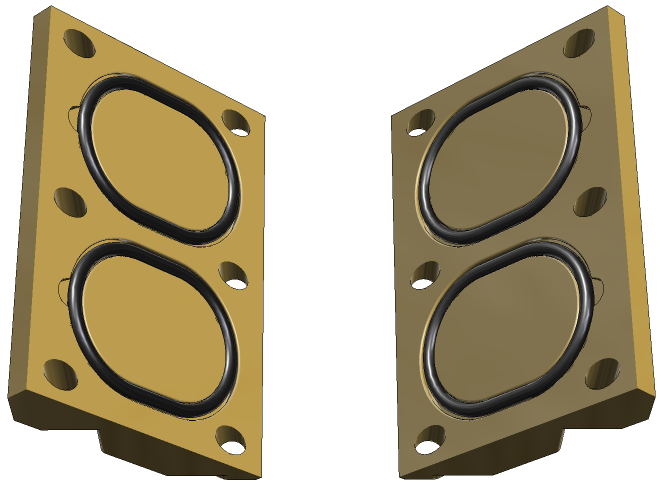
- Inspect the mirror O-rings and replace them if any O-rings are cracked.
- To remove an O-ring, dislodge it with a toothpick. Extra O-rings are in the spares kit. Press the new O-ring into the mirror.
- Install the mirrors.
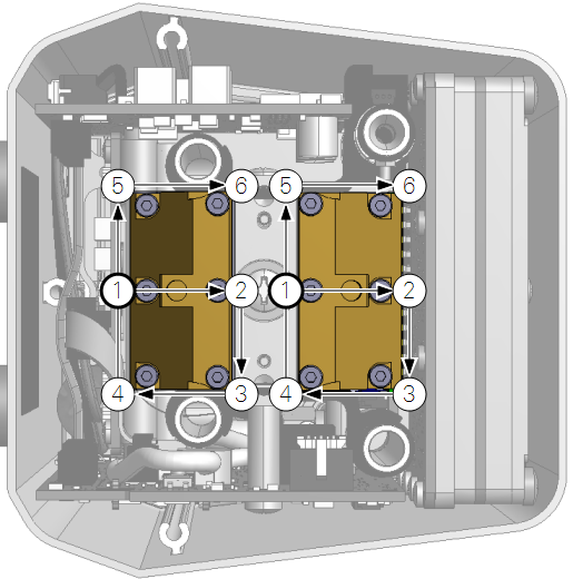
- Tighten the mirror screws snugly in a spiral sequence starting with a middle screw. If you have a torque screwdriver, tighten the screws to 45 inch ounces (0.32 N•m) force. Repeat the tightening sequence.
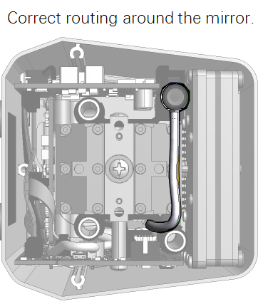
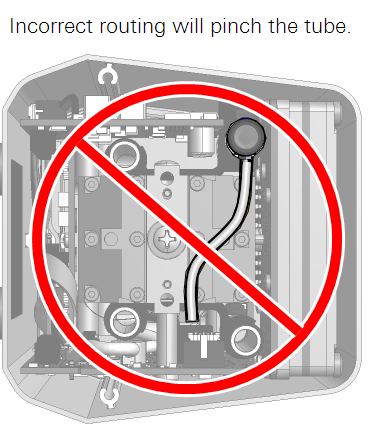
- Install the pressure tube.
- Gently press it into place. Route the tube around the mirror so it doesn't become pinched when you install the bulkhead cover.
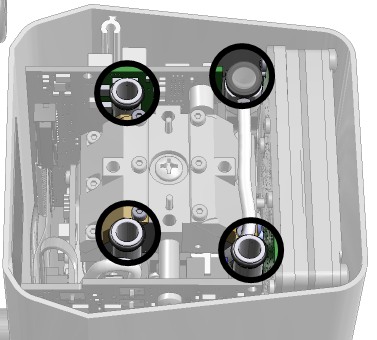
- Check the condition of the four bulkhead O-rings.
- If they are cracked or brittle, replace them with O-rings from the spares kit (part number 192-14314).
- Install the bulkhead.
- When positioning the bulkhead, be sure that the four tubes and their O-rings are aligned correctly with the openings in the bulkhead. Be sure the filter screen is in place.
- Tighten the screws snugly. If you have a torque screwdriver, tighten them to 22 inch lbs (2.5 N•m).
- Check the condition of the O-rings on the heat exchanger assembly.
- If they are cracked or brittle, replace them with O-rings from the spares kit (part number 192-14314).
- Install the heat exchanger assembly.
- Tighten the screws snugly. If you have a torque screwdriver, tighten them to 22 inch lbs (2.5 N•m).
- Install the chamber.
- Perform the sensor tests.
- Under Start Up > System Tests, select Sensor Check. The most important one is the leak test.
- Set the Zero and Span calibrations.
- See User calibration - zero and span.