The LI-7550 Analyzer Interface Unit, when used with the LI-7700, extends the functionality of the instrument by providing additional data input and output options, including data logging to a removable USB storage device, Ethernet communication and data transfer, RS-232 serial communications, SDM data output, six high-speed scalable Digital-to-Analog converters (16 bit, ±5V), and four additional analog inputs (16 bit, differential, ±5V).
Note: The LI-7550 is a standard component of the LI-7500A/RS or LI-7200/RS CO2/H2O Analyzers. In these configurations, the LI-7550 requires embedded firmware that is specific to the LI-7500A/RS and LI-7200/RS, and certain features described here are not available. This section describes the functionality that is provided when the LI-7550 is running LI-7700 embedded firmware. Contact LI-COR for more information.
What's what
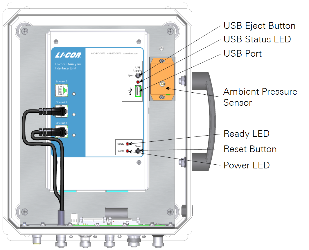
- USB Eject Button: Press to eject the USB drive.
- USB Status LED: Indicates the status for the flash drive:
-
- Solid: Drive mounted, not logging.
- Rapid Blink: Logging data.
- Slow Blink: Error. Eject and reinsert the drive.
- Off: Drive not mounted; OK to remove.
- USB Port: A USB drive must be installed in order to log data. Two compatible drives are in the spares kit.
- Ready LED: On when the instrument is warmed up and ready to measure.
- Reset Button: Press to restart the LI-7550 and gas analyzer.
- Power LED: On when the instrument is powered on.
The connector panel has connectors for the sensor head and other cables.
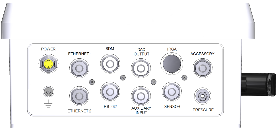
- POWER: For the power cable (9975-030). Apply 10.5 to 30 VDC, 30 W minimum to power on the instrument.
- ETHERNET 1 and 2: Sealed connectors for network cables. Typically connected to cable part numbers 392-10107 and 392-10108 to connect with other networked devices through the Brainboxes SW-508 network switch.
- SDM: Connector for an SDM outputs using cable 392-10093.
- DAC OUTPUT: Connector for analog outputs. Connects to cable 392-10109 or the 7550-101 Auxiliary Sensor Interface.
- IRGA: Connector for the data cable from the gas analyzer.
- ACCESSORY: Connector for accessories, including the flow module and heated intake tube. A splitter cable is required to use both.
- GROUND lug: Connects the gas analyzer to an earth ground.
- RS-232: Connector for serial data using cable 392-10268.
- AUXILIARY INPUT: Connector for inputs. Connects to cable 392-10109 or the 7550-101 Auxiliary Sensor Interface.
- SENSOR: Connector for air temperature thermistor.
- PRESSURE: Vent air pressure sensor.
Interior label
Inside the LI-7550 there are three Ethernet ports and one port for a USB data storage device. Two of the Ethernet ports are connected to the Ethernet ports on the connection panel. It does not matter which ports these internal cables are connected to. The third port is not connected to the panel, but can be used to connect an Ethernet device, such as a laptop computer.
LI-7550 spare parts kit
Part Number 9975-023
The LI-7550 Analyzer Interface Unit has a spare parts kit. It includes the cables and mounting bracket. As you become familiar with the analyzer you will learn which items to keep close at hand and which items can be stored away.
| Description | Quantity | Part Number |
|---|---|---|
| Power Cable (5 m) | 1 | 9975-030 |
| 16 GB USB Flash Drive | 2 | 616-10723 |
| Mounting Kit | 1 | 9979-022 |
| RS-232 Serial Cable (5 m) | 1 | 392-10268 |
| Analog Input/Output Cable (5 m) | 1 | 392-10109 |
| Ethernet Cable (8-pin Turck® Connectors; 5 m) | 1 | 392-10108 |
| Ethernet Adapter Cable, 8-pin Turck to RJ45 | 1 | 392-10107 |
| Standard Ethernet Cable (2.1 m) | 1 | 616-06116 |
| SDM Cable (5 m) | 1 | 392-10093 |
| 5 Amp Fuse | 2 | 439-04214 |
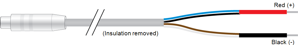
- Power Cable - The power cable (part number 9975-030) is 5 m long. It has a 4-pin female terminal plug that attaches to the connector labeled POWER on the LI-7550 Analyzer Interface Unit connection panel. The power cable is terminated with black (-) and red (+) leads for connection to a user supplied 10.5-30 VDC power supply.
- Ethernet Cables - Two Ethernet Cables (part number 392-10107 and 392-10108) are included for connecting to a Local Area Network (LAN) or computer via an Ethernet port. Part number 392-10108 is terminated on both ends with male Turck connectors. One end attaches to the LI-7550 Analyzer Interface Unit, and the other end attaches to the short (0.3m) Ethernet adapter cable (part number 392-10107). The short cable is terminated with an RJ45 Ethernet connector, which plugs into an Ethernet wall socket or a computer’s Ethernet port.
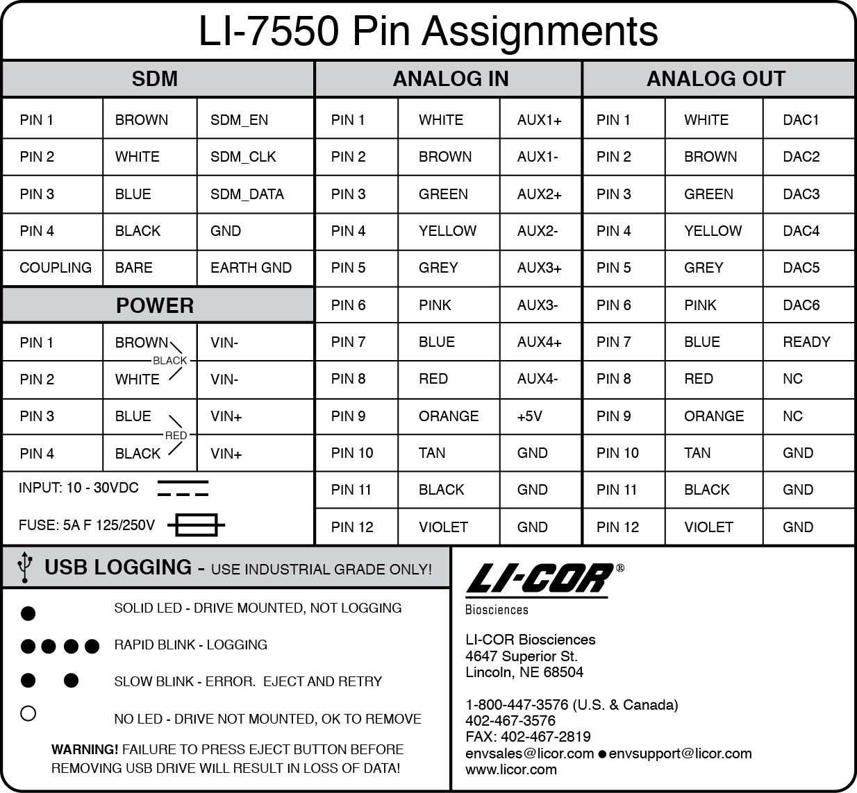
- SDM Interface Cable - The SDM interface cable (part number 392-10093) is for connecting to Campbell® Scientific, Inc (Logan, Utah) dataloggers using the Synchronous Devices for Measurement (SDM) data communication protocol. SDM communications are enabled in the Campbell Scientific datalogger. The SDM interface cable plugs into the connector labeled SDM on the LI-7550 Analyzer Interface Unit connection panel. See SDM output for modes and configuration information. SDM wire colors and pin assignments are given in Figure 5‑3.
- USB Flash Drive – Industrial grade USB flash drive is included in the spares kit. Additional drives are available for purchase directly from LI-COR.
- Serial RS-232 Cable - The RS-232 cable (part number 392-10268) is a null modem cable with a 6-pin female circular connector that attaches to the RS-232 connector on the LI-7550 Analyzer Interface Unit connection panel. The other end has a standard DB-9 female connector for direct connection to a computer. Alternatively, the RS-232 cable can be connected to an RS-232-to-USB adapter to use the RS-232 connection with a USB port.
- Analog Input/Output Cable - The Analog Input/Output Cable (part number 392-10109) is for connecting user-supplied sensors to LI-7700 or LI-7550 analog inputs and/or for connecting the LI-7550 analog outputs to a data logger. The pin assignments and wire colors are shown in Figure 5‑3.
- When used for analog inputs to the LI-7550, the cable connects to the AUXILIARY INPUT connector on the LI-7550 connection panel. See Analog inputs (LI-7550).
- When used for analog outputs from the LI-7550, the cable connects to the DAC OUTPUT connector on the LI-7550 connection panel. See Analog outputs (LI-7550).
- If used for analog inputs on the LI-7700, the cable connects to the ANALOG INPUT connector on the LI-7700 connector panel. See Analog inputs (LI-7700).
The optional weatherproof Auxiliary Interface Unit (part number 7550-101) can be used in place of this cable. Only one Analog Input/Output cable is included with the LI-7550. If you intend to use both the analog input and analog outputs on the LI-7550 you can acquire an additional 392-10109 cable or use the 7550-101 Auxiliary Sensor Interface.
Basic setup
This section covers basic operation of the LI-7700 with the LI-7550 Analyzer Interface Unit.
Powering on
The LI-7550 has no power switch – it turns on when power is supplied through the power cable (10.5-30 VDC, 2 amps). When power is supplied the Power LED on the indicator panel will illuminate, and it will stay lit as long as power is supplied, The Ready LED will turn on when the embedded software has booted up and the LI-7550 is ready to communicate with a computer.
Connecting to the LI-7700 and LI-7550 (Ethernet)
If you are using an LI-7700 with an LI-7500A/RS/DS or LI-7200/RS to log complete eddy covariance datasets on the SmartFlux 2 or 3 System, you do not need to follow this section. If you are using the LI-7700 with an LI-7550 in the methane configuration, follow this procedure to establish communication between the two devices.
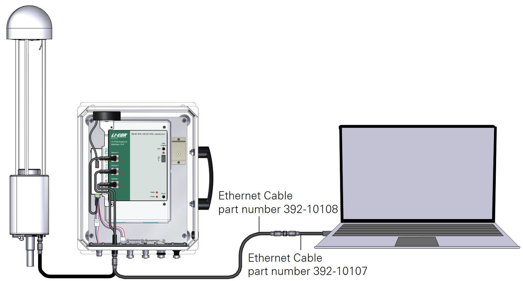
The LI-7700 connects to the LI-7550 using the Ethernet cable (part number 392-10108), which terminates with Turck® connections on both ends. Attach one terminal to the Ethernet connection on the LI-7700 and the other to either the Ethernet 1 or 2 terminals on the LI-7550 connection panel. You can now connect the LI-7550 to a computer or network with the vacant Ethernet port on the LI-7550 connection panel (using the Ethernet cables part number 392-10108 and part number 392-10107 in series), or the vacant Ethernet port inside the box (with a user-supplied Ethernet cable).
Getting an LI-7700 to communicate with an LI-7550
Note: The LI-7550 can run two versions of software. The methane version is required when using the LI-7700 with the LI-7550 exclusively. The CO2/H2O version is required when using the LI-7700 with the LI-7500A/RS or LI-7200/RS CO2/H2O analyzer and SmartFlux 2 System.
Follow the steps below to get the LI-7700 to communicate with the LI-7550.
- Power on both the LI-7700 and LI-7550.
- Connect LI-7700 and LI-7550 with the Ethernet cable, as described above. Connect the LI-7550 to your computer or network with the Ethernet cable.
- Launch the Windows software but do not connect to an instrument.
- Click the Help icon
 and click About.
 -

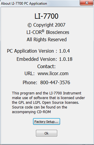
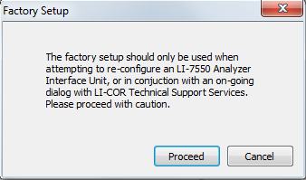
- In the About dialog box (below, left) click Factory Setup… then click Proceed in the warning that appears (below, right).
- In the Factory Setup dialog box you should see both the LI-7700 and the LI-7550, similar to the figure below.
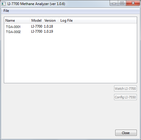
- Click on the LI-7550, then click the Config LI-7550 button.
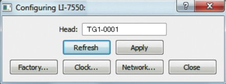
- In the resulting dialog box, confirm that the text in the field called Head: matches the text on the Factory Setup display for the name of the LI-7700 Analyzer (it is not case sensitive), or edit the field so they match.
- In this case, the name is “TG1-0001”, as shown below.
- If you changed the name, click the Apply button to confirm the name change.
- Restart both devices by disconnecting and reconnecting the power supply.
- Confirm that the two devices are communicating by connecting to the LI-7700 with the PC software. Insert a USB storage device into the LI-7550 USB port.
- If the USB device appears in the USB Logging window, both are configured correctly.
Identifying the LI-7550 firmware version
Which software is the LI-7550 running? There is a sticker inside the LI-7550 that indicates the software version that was loaded at the factory (methane for the LI-7700, CO2/H2O for the LI-7500A/RS or LI-7200/RS). You can also find the software version by following the steps below:
- Connect the LI-7550 Analyzer Interface Unit to a suitable power supply, then connect the Ethernet cables to enable communication with your computer.
- Launch the LI-7700 PC software but do not connect to an instrument.
- Click the Help button and click About.
- In the About dialog, click Factory Setup…, then click Proceed in the warning dialog. You should see window similar to the figure below.
-
- The LI-7550 will be listed. If the LI-7550 is configured for the LI-7700, under the Model heading, it will read LI-7550 (LI-7700). If it is configured for an LI-7500A/RS or LI-7200/RS, it will read LI-7550 (LI-7500A/RS/7200RS).
If the LI-7550 is configured to support an LI-7500A/RS or LI-7200/RS, you can log LI-7700 and Auxiliary Input 1-4 data to the LI-7550 USB device in the same data file as CO2/H2O analyzer data. However, you cannot set up the Auxiliary Inputs 5-8, SDM, RS-232, or DAC outputs from the LI-7700 PC software, nor can you output methane analyzer data using SDM, RS-232, or DACs. Instead, use the LI-7500A/RS or LI-7200/RS PC software to configure those channels.
In this configuration, the LI-7700 PC software will prohibit you from configuring LI-7550 Auxiliary Inputs, opening the Configure LI-7550 Outputs window, or opening the USB… window from the LI-7700 PC software. Conversely, if the LI-7550 is formatted to operate with an LI-7700, you will have access to all functions in the software, but it will be unable to communicate with an LI-7500A/RS or LI-7200/RS.
When using the LI-7700 in conjunction with an LI-7500A/RS or LI-7200/RS using a shared LI-7550 (configured for CO2/H2O), data output is limited to Ethernet. All data are logged to files on the USB storage device.
Note: The procedures described in Connecting to the LI-7700 and LI-7550 (Ethernet) are only available when the LI-7700 and LI-7550 are connected using the Ethernet port. While the RS-232 connection does allow you to configure the LI-7700, and data can be output using the serial connection, the Factory Setup application (also known as the LI-7700 Finder Application) will not find an LI-7700 or LI-7550 that is connected via the serial connection.
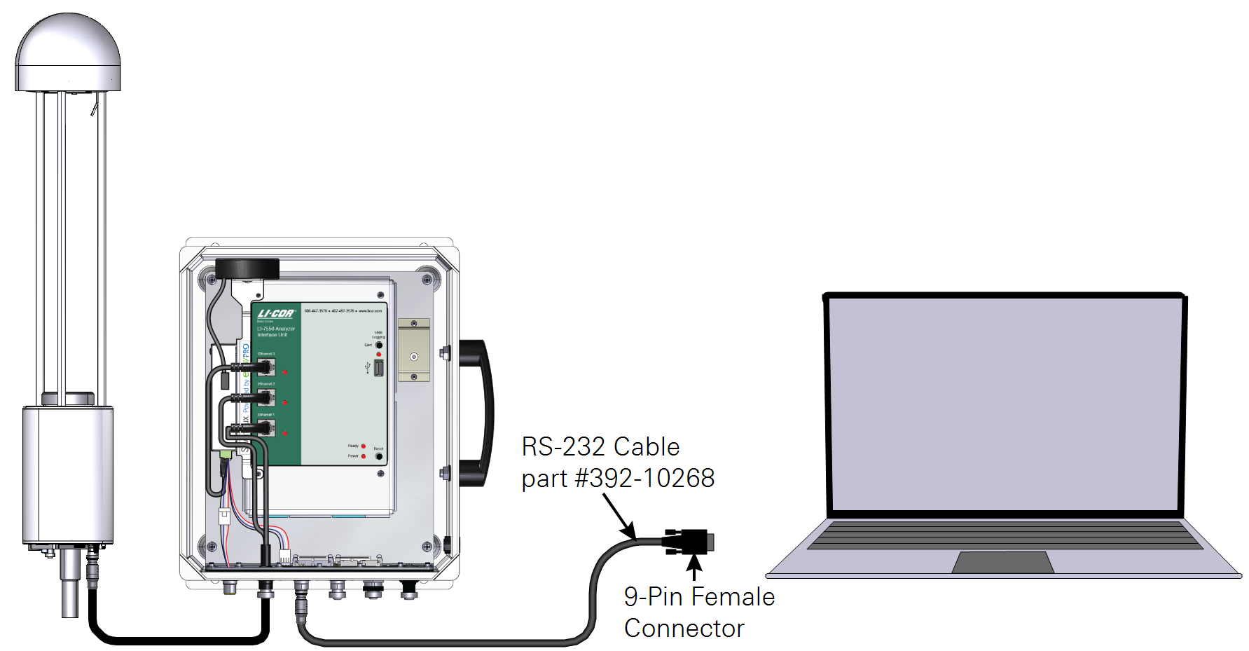
The LI-7550 enables RS-232 communications with the LI-7700. Prior to connecting with RS-232, enable communication between the LI-7550 and LI-7700 (see Getting an LI-7700 to communicate with an LI-7550). Then, connect the LI-7550 to your computer’s RS-232 connection with the cable (part number 392-10268) and connect the LI-7700 to the LI-7550, as shown below. An RS-232-to-USB adapter may be required (392-07713) for computers that to not have an RS-232 port.
To connect, launch the LI-7700 software, click Connect, check RS-232, and choose the COM port (between 1 and 32) that the instrument is connected to. Click Connect.