Configuring the LI-7550 clock, outputs, and inputs
Note: If the LI-7550 is configured to support an LI-7200/RS or LI-7500A/RS, it will not be possible to configure Auxiliary Inputs (Aux5 to Aux8), SDM, RS-232, or DAC outputs from the LI-7700 PC software. The software will prohibit you from opening the Configure LI-7550 Outputs window. These features can be configured in the CO2/H2O analyzer software; however, they will only apply to the CO2/H2O analyzer data.
The LI-7550 is configured through the LI-7700 software. When settings are configured in the LI-7700 software, this information is stored in the LI-7550. Then the LI-7550 pulls this information from the LI-7700 when the two components are connected and powered up.
LI-7550 clock
The LI-7550 clock is separate from the LI-7700 clock, but it also uses Unix (POSIX) time and the Precision Time Protocol. When the two components are used together without the LI-7500A/RS/DS or LI-7200/RS, set the LI-7700 clock to automatic and the LI-7550 clock to preferred. This will ensure that the time stamp comes from the LI-7550. The LI-7550 clock has the same setting options as the LI-7700 clock. To view or set the time in the LI-7550:
- Connect the LI-7550 to your computer using the Ethernet, or to your network or computer using the Ethernet cable (RS-232 does not support this).
- Launch the LI-7700 software, click the Help button
 , and select About.
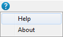
- Click Factory Setup… and click on Proceed after reading the warning.
- Select the Base Box (under the Model heading it will be called LI-7550) and click on Config LI-7550.
- Click Clock….
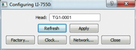
- Configure the clock settings as desired. In the Precision Time Protocol frame, choose Automatic, Slave Only, or Preferred Clock. Preferred is the recommended setting when using the LI-7550 or SmartFlux System with the LI-7700.

- Apply the settings and close the window.
LI-7550 outputs
The four output options are described below, including Ethernet, SDM, RS-232, and analog.
Ethernet output
Ethernet output from the LI-7700/7550 combination is configured in the same way as LI-7700 Ethernet output. This is described in Logging data to a computer.
SDM output
SDM addressing allows for multiple SDM-compatible peripherals to be connected to a single Campbell® Scientific, Inc datalogger. To log the SDM output from the LI-7700, first set up the LI-7700 using the PC software, then program the datalogger to poll the LI-7700 for data. The blue wire (SDM_DATA) should be connected to datalogger terminal C1, white (SDM_CLK) to terminal C2, and brown (SDM_EN) to C3. Black and bare leads attach to datalogger ground terminals.
Caution: If the LI-7550 is configured for SDM outputs when used with a LI-7700, USB logging should not be undertaken because system performance may be adversely affected when the USB drive is full.
Time Delay
The SDM output has a fixed time delay of 1 second.
Configuring SDM Output
Caution: If the LI-7550 is configured for SDM outputs when used with a LI-7700, USB logging should not be undertaken because system performance may be adversely affected when the USB drive is full.
- In the LI-7550 Outputs dialog (
 ), under the Setup tab, choose an SDM address between 0 and 14. Address 15 is reserved for the SDMTrigger instruction.
- Set the LI-7700 output rate in the Manual Controls (
 ) window. Select an output rate (e.g., 10 Hz) that is twice the desired bandwidth (e.g., 5 Hz) and click Apply or OK.
Configuring the datalogger
SDM communications are enabled in Campbell Scientific® dataloggers with the SDM LI7700 instruction. The basic instruction will resemble:
LI7700 (Destination,Repetitions,SDM Address,Mode)Where Destination is the name of the input variable, an array, in which to store the data from the LI-7700, Repetitions refers to the number of LI-7700s that will be sampled sequentially using sequential addresses, SDM Address specifies the SDM address of the LI-7700 and needs to match the address set in the LI-7700 software, and Mode refers to the data that will be retrieved from the LI-7700. Seven data modes are available (see Table 5‑1).
An example of the instruction is given:
LI7700 (CH4(1),1,0,1)Where CH4 is the destination name is for the first location in the array, 1 is the number of LI-7700s polled, 0 is the SDM Address, and 1 is Data-Normal from Table 5‑1.
RS-232 output
When using RS-232 output, first set the LI-7700 output rate in the Manual Controls window (see Output rate).
Click Configure LI-7550 Outputs to access the outputs window. The RS-232 tab is used to set the LI-7700 RS-232 port configuration for serial data output. After selecting the desired variables click Apply; the LI-7700 will begin to send data out the RS-232 port according to these parameters.

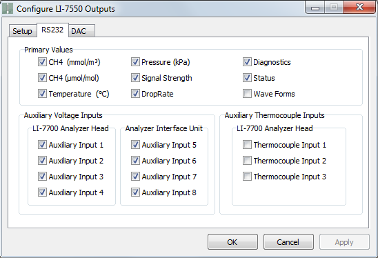

Since this controls a serial data stream, there is no concept of files or splitting files. The baud rate is set to 57,600. When sending data through the serial connection, note that the baud rate may limit the number of samples that can be output. Therefore, you may have better results if you do not log the Diagnostics or Status data.
Analog outputs (LI-7550)
The LI-7550 has the capacity to output up to six variables on Digital-to-Analog Converter (DAC) channels 1-6. Click Configure LI-7550 Outputs to access the outputs dialog. The DAC tab allows you to configure the DAC output channels by specifying the source that drives the analog signal (CH4 mmol m‑3, CH4 µmol mol-1, temperature, pressure, signal strength, and set point), the measured value that corresponds to 0V, and the measured value that corresponds to 5V.
For example, DAC1 can be configured to output a voltage signal for CH4 with 0 mmol m‑1 proportional to 0V, and 5 mmol m-1 equal to 5V by setting the dropdown menu to read CH4 (mmol m-1) and entering 0 and 5 in the 0V and 5V fields respectively.
Note: The LI-7700 analog output signals update at 300 Hz to minimize jitter.
When using the analog outputs, set the LI-7700 output rate to twice the desired bandwidth (in the Manual Controls window). Configure your data storage device to sample at a rate that is equal to or greater than the LI-7700 output rate.
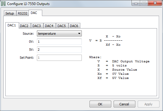
The Set Point field will be available when the Set Point option is selected in the Source menu. Set point is a DC output value for testing DACs and data storage devices. The output voltage is converted via:
5‑1Output Voltage (V) = 5 V * (Set Point Value – 0 V Value)/(5 V Value – 0 V Value)
Time delays
The analog outputs on the LI-7550 are delayed by 1 second to account for network latencies. The total delay at a particular output rate is increased by the averaging filter according to the expression:
5‑2

The table below summarizes the delays:
| Output Rate | Frequency Response (‑3db) | Analog Output Signal Delay |
|---|---|---|
| 40 Hz | 20 Hz | 1.0 s |
| 20 Hz | 10 Hz | 1.0125 s |
| 10 Hz | 5 Hz | 1.0375 s |
| 5 Hz | 2.5 Hz | 1.0875 s |
| 2 Hz | 1 Hz | 1.2375 s |
| 1 Hz | 0.5 Hz | 1.4875 s |
Hardware configuration
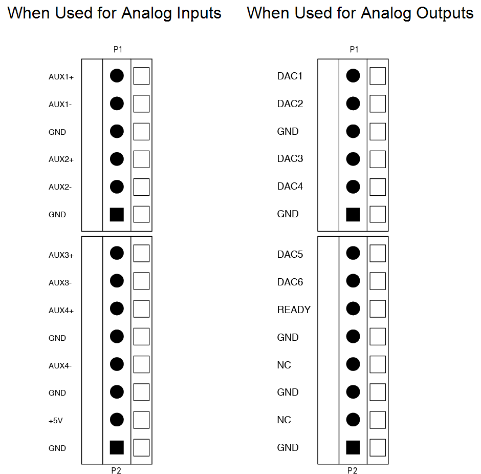
Both the Analog In/Out Cable (part number 392-10109, provided) and the 7550-101 Auxiliary Sensor Interface (optional) can be used to distribute the analog output signals. Pin and terminal assignments for both are given in Table 5‑3. The schematic below represents the terminal strip inside the 7550-101 when it is configured for analog outputs.
| When connected to the LI-7550 analog outputs1 | ||||
|---|---|---|---|---|
| 7550-101 Auxiliary Sensor Interface | Description | Analog In/Out Cable (part number 392-10109) | ||
| Terminal | Outputs | Wire Color | Pin | |
| 1 | DAC1 | DAC channel 1 positive | White | Pin 1 |
| 2 | DAC2 | DAC channel 2 positive | Brown | Pin 2 |
| 3 | GND | Ground | Tan | Pin 10 |
| 4 | DAC3 | DAC channel 3 positive | Green | Pin 3 |
| 5 | DAC4 | DAC channel 4 positive | Yellow | Pin 4 |
| 6 | GND | Ground | Tan | Pin 10 |
| 7 | DAC5 | DAC channel 5 positive | Grey | Pin 5 |
| 8 | DAC6 | DAC channel 6 positive | Pink | Pin 6 |
| 9 | READY | Analyzer Ready | Blue | Pin 7 |
| 10 | GND | Ground | Black | Pin 11 |
| 11 | NC | No connection | Red | Pin 8 |
| 12 | GND | Ground | Violet | Pin 12 |
| 13 | NC | No connection | Orange | Pin 9 |
| 14 | GND | Ground | Tan | Pin 10 |
Analog inputs (LI-7550)
Analog inputs (Option 2) are configured from the Configure Auxiliary Inputs window. These are labeled Aux5 through Aux8 in the lower block of inputs. Two mathematical conversions of analog input voltages can be configured in the dialog box: 1) a third order polynomial or 2) a Steinhart equation (for measuring temperature with a thermistor).
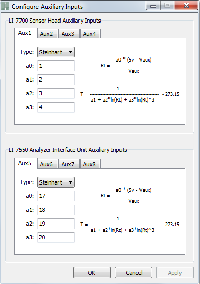
These are described in detail in Analog inputs (LI-7700). After configuring the inputs, click Apply or OK to implement the settings.
As mentioned previously, the 7550-101 can serve as a terminal strip for analog inputs or outputs for the LI-7550. Alternatively, the Analog Input/Output Cable (part number 392-10109) can be used.
To use LI-7700 inputs (see Analog inputs (LI-7700)) with the 7550-101, be sure the LK1 jumper is positioned over the two pins nearest the LI-7550 label. Below we describe how to configure the 7550-101 and the corresponding wires/pins in the Analog Input/Output Cable for LI-7550 analog inputs.
Auxiliary sensor interface terminals
To gain access to the inside of the 7550-101, loosen the four #1 Philips screws on each corner of the top cover. Remove the cover. The schematic below shows the interior of the interface box. The terminal strips connections are shown below:
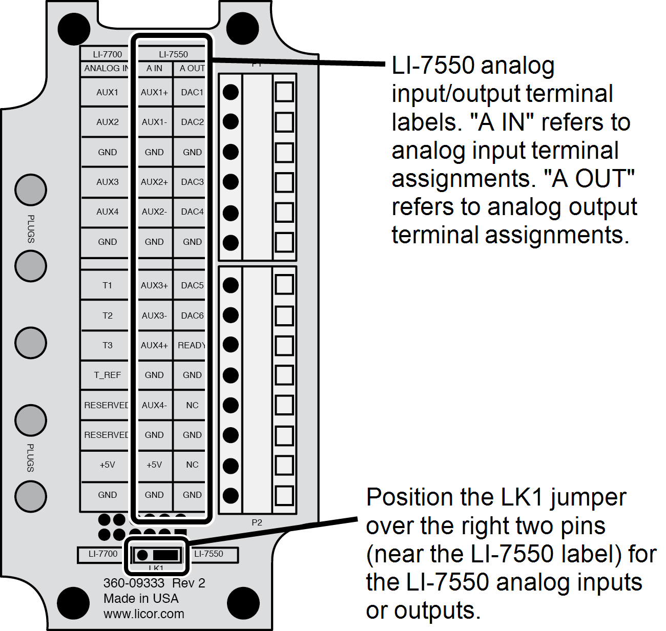
Table 5‑4 shows Auxiliary Sensor Interface input assignments and corresponding wire colors for the input cable.
| When connected to the LI-7550 analog inputs2 | ||||
|---|---|---|---|---|
| 7550-101 Auxiliary Sensor Interface | Description | Analog In/Out Cable (part number 392-10109) | ||
| Terminal | Inputs | Wire Color | Pin | |
| 1 | AUX1+ | Auxiliary Input 1 positive | White | Pin 1 |
| 2 | AUX1- | Auxiliary Input 1 negative | Brown | Pin 2 |
| 3 | GND | Ground | Tan | Pin 10 |
| 4 | AUX2+ | Auxiliary Input 2 positive | Green | Pin 3 |
| 5 | AUX2- | Auxiliary Input 2 negative | Yellow | Pin 4 |
| 6 | GND | Ground | Tan | Pin 10 |
| 7 | AUX3+ | Auxiliary Input 3 positive | Grey | Pin 5 |
| 8 | AUX3- | Auxiliary Input 3 negative | Pink | Pin 6 |
| 9 | AUX4+ | Auxiliary Input 4 positive | Blue | Pin 7 |
| 10 | GND | Ground | Black | Pin 11 |
| 11 | AUX4- | Auxiliary Input 4 negative | Red | Pin 8 |
| 12 | GND | Ground | Violet | Pin 12 |
| 13 | +5V | +5V supply (10 mA max.) | Orange | Pin 9 |
| 14 | GND | Ground | Tan | Pin 10 |
Electrical connections
All analog devices connected to the 7550-101 Auxiliary Sensor Interface must be referenced to the ground (GND) connection when connected to the LI-7550 analog inputs. Some examples are shown below.
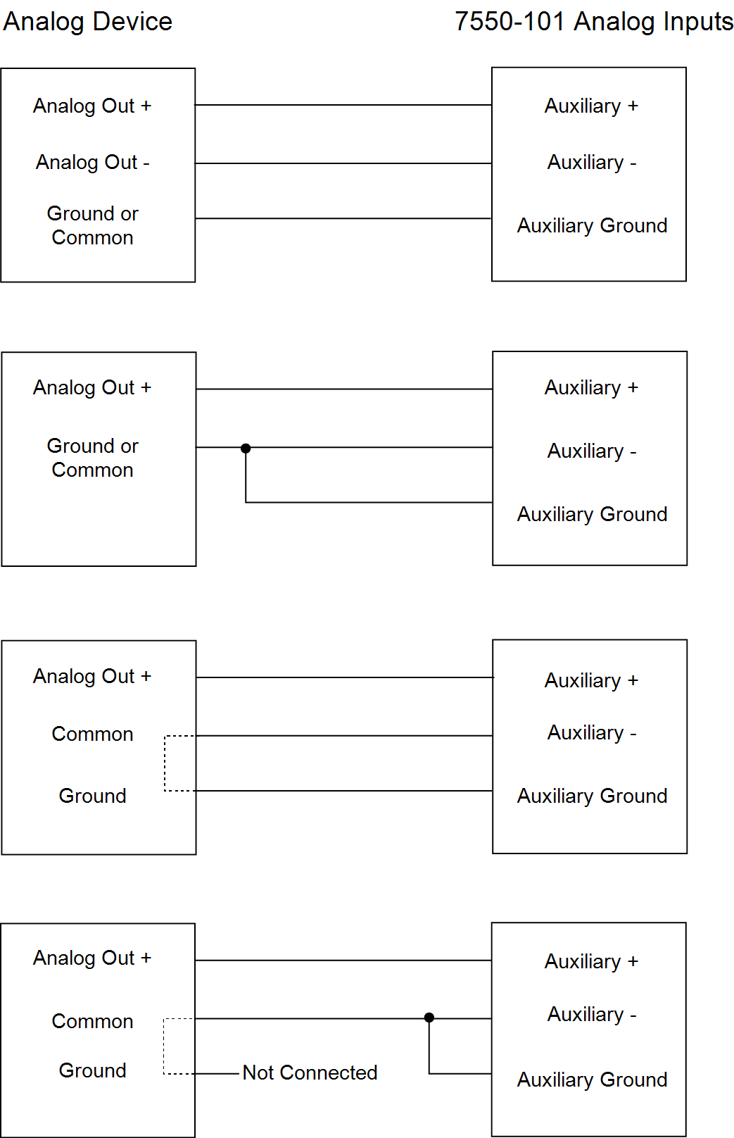
Connection Notes:
- All LI-7550 auxiliary analog input ground connections are internally connected together.
- All LI-7550 auxiliary analog output ground connections are internally connected together.
- Analog devices with both ground and common outputs can share these outputs with their power supply ground.
- LI-7550 analog inputs are electrically isolated from the LI-7550 power input.
- LI-7550 analog outputs are electrically isolated from the LI-7550 power input and isolated from the analog inputs.
For additional 7550-101 & Analog Input/Output usage instructions, see Analog inputs (LI-7700).
Analog input time delays
Data from Auxiliary Inputs 5-8 (available only on the LI-7550) have a fixed time delay of 1 second. These values are shifted together in the data files by 1 second from data acquired with the LI-7700, Auxiliary Inputs 1-4, and the thermocouple inputs.
Logging data to the USB storage device
Caution: If the LI-7550 is configured for SDM outputs when used with a LI-7700, USB logging should not be undertaken because system performance may be adversely affected when the USB drive is full.
USB data storage (with the LI-7550) is configured in the Logging frame. These settings are configured through the LI-7700 PC software and implemented automatically when the LI-7700 is connected with an LI-7550 and both instruments are powered up.
To log data to a LI-7550:
- Click the USB… button in the Logging frame.

- In the Configure USB Log Data dialog box, select the variables that you would like to log and click Apply.
- Auxiliary Inputs 1-4 and Thermocouple Inputs 1-3 are described in Analog inputs (LI-7700), and Auxiliary Inputs 5-8 are described in Analog inputs (LI-7550).
- In the Log File frame, choose to Log Status Columns to a separate file or to the data file.
- Then choose whether to split the file, and how often (from 15 minutes to 24 hours). Click Apply.
- To begin logging data immediately click a Start button (
 ) or (
 ).
). - Otherwise, logging will begin automatically when a USB storage device is inserted into the USB port, or when the instruments are restarted (if a suitable USB drive is present).
- To remove the USB storage device press the Eject button in the LI-7550. The LI-7550 will stop writing data until another USB device is inserted, after which it will immediately resume logging data.
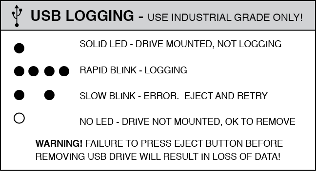
The LED by the USB port indicates the status of data logging with a blinking pattern, as described in Figure 5‑9.
About USB devices
Important: We recommend that you use an industrial rated USB flash drive provided by LI-COR. Non-industrial rated flash drives can fail, causing you to lose data.
Many user-supplied industrial grade flash drives are compatible with the LI-7550, but some devices with custom drivers or encryption may not work. The drive must be formatted to support FAT or Linux ext3 file systems. FAT32 is recommended over FAT16. Contact LI-COR to find out if your USB drive is compatible with the LI-7550.
Note: Data logging will stop when the storage device has reached capacity, but will automatically resume when a USB storage device is reattached, assuming it has storage space available. Data logging also automatically starts when the instrument starts up, following a power interruption for example. Storage devices that are being used for the first time may take about 60-90 seconds to initialize before data will be written to the device.
Storage capacity
With a 4 GB USB flash drive, logging all 20 variables at 10 Hz (samples/second), the drive can log uncompressed data for about 22 days before becoming full. See Table 5‑5 for more details.
| Variables Logged | Time to fill a 4 GB drive (no compression)3 |
|---|---|
| All (including status and diagnostics) | ~22 days |
| All (including status but not diagnostics) | ~27 days |
| CH4 (mmol/m3), Temp., Pressure, Signal Strength, Drop Rate, Status, and Aux. Inputs 1 to 4 | ~44 days |
If you log compressed files in the .ghg format, including data provided by the LI-7500A/RS/DS or LI-7200/RS and the LI-7700 (53 columns of data) at 10 Hz, 4 GB of data will accumulate over about 46 days.
Mounting the LI-7550 Analyzer Interface Unit
Two mounting plates (part number 9979-022) are included that can be used to mount the LI-7550 using band clamps to secure the box to a tripod or other post. There are holes in the four corners of the box, as well, that can be used to attach the box directly to a flat surface, if desired.
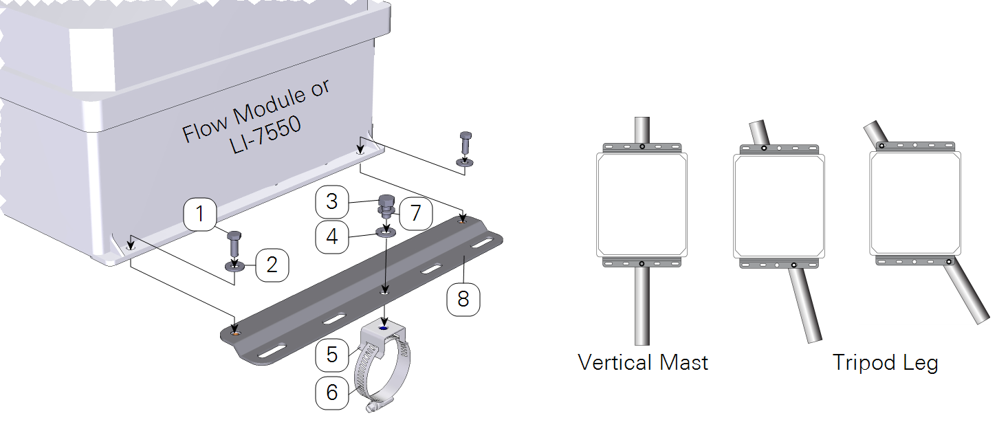
| Item | Qty. | Part Number | Description |
|---|---|---|---|
| 1 | 4 | 150-12943 | Hex Head Bolt M6x1 × 16 mm |
| 2 | 4 | 167-02054 | Flat Washer 1/4 x 5/8” |
| 3 | 2 | included w/ item #4 | Hex Head Bolt 5/16-24 × 1/2” |
| 4 | 2 | included w/ item #4 | Flat Washer 5/16” |
| 5 | 2 | 235-13234 | Flared-Leg Mounting Bracket |
| 6 | 2 | 300-13293 | Band Clamp 9/16” |
| 7 | 2 | 167-05635 | Split Washer 5/16” |
| 8 | 2 | 9879-045 | Mounting Plate |
The mounting plates and band clamps are designed to accommodate a square or circular mounting post of up to 2.75" in width (diameter). Hardware is included to attach the mounting plates to the Analyzer Interface Unit using 4 hex head bolts (part number 150-12943). The hose clamp mounting brackets are attached to the mounting plates, and then the band clamps can be inserted through the holes in the hose clamp mounting brackets, and tightened around the post, as shown in Figure 5‑10. The hose clamp mounting brackets can be inserted through any of the holes in the mounting plates to accommodate a variety of mounting options for the LI-7550.
There are some additional considerations that should be taken into account when locating the Analyzer Interface Unit, including:
- The data cable that connects to the sensor head is 5 meters in length; determine the height at which the sensor head will be mounted, and plan to mount the Analyzer Interface Unit accordingly. This cable could be up to several hundred feet long.
- The thermal properties of the Analyzer Interface Unit are such that it is OK to place the box in direct sun.
- The power cord provided is 5 meters long. Longer cables can be purchased through distributors of Turck, Inc.
- For lightning protection run an independent bonding wire from the instrument ground to the earth.