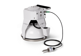
With this accessory, a syringe is used to extract a small sample of a gas stream for estimating the flux of trace gas, such as ammonia (NH3), nitrous oxide (N2O), isotopic species, etc. The concentration of the gas species for those collected air samples can be subsequently analyzed with gas chromatography or mass-spectroscopy methods in a laboratory. The flux of the gas species can be estimated based on the rate of change of concentration between sub-samples and other required variable data logged by the Smart Chamber.
Because the Smart Chamber provides complete self-control of gas flow to and from the chamber, the sampling kit can be used without a gas analyzer or external pump. As the concentration of trace gases builds in the closed chamber, a well-mixed portion is continuously pumped through the compression fitting and can be sampled without leaks through the self-sealing septum at regular intervals throughout the repetition.
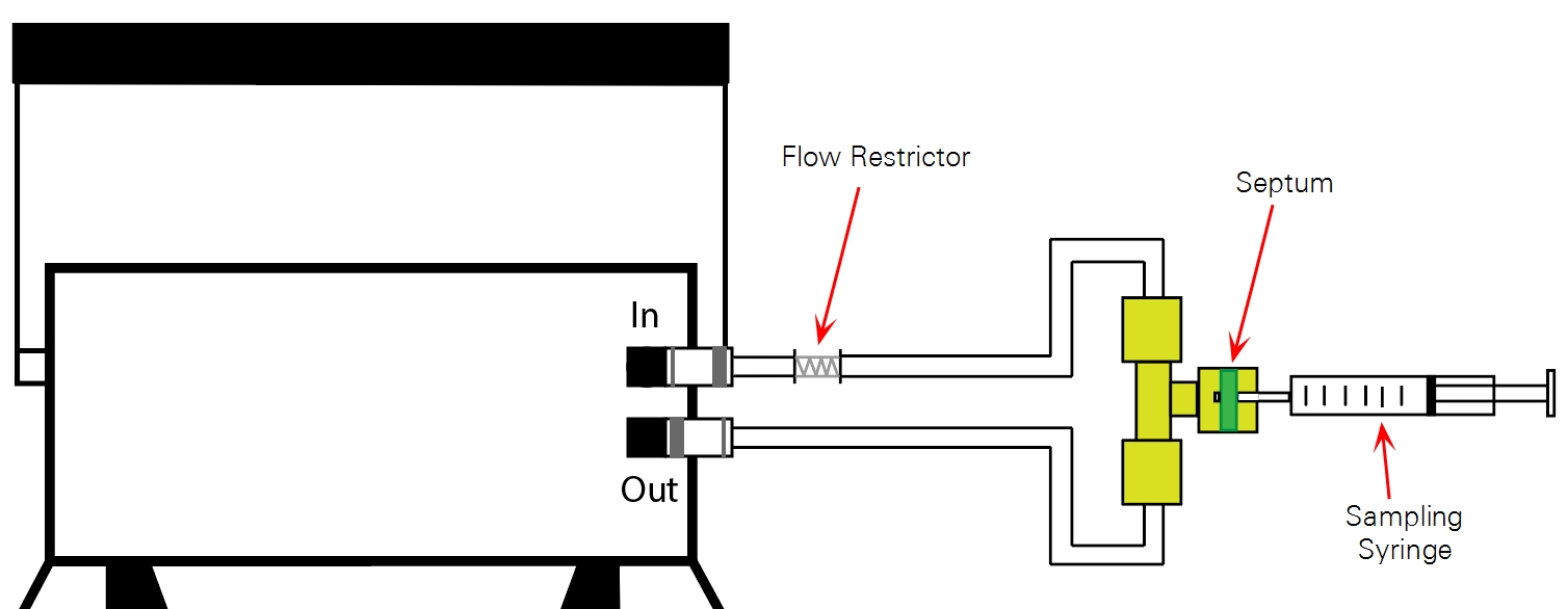
Instructions for assembling the Trace Gas Sampling Kit are included in the kit. Connect the tubing to your Smart Chamber according to the diagram above.
Total system volume
Total system volume is a critical constant for flux calculations in a closed system. Calculate tube volume by measuring the total length of tubing used to attach the Trace Gas Sampling Kit, add this to the volume of the chamber (4424.1 cm3), and enter the total volume in the software. The Bev-A-Line® tubing include with the kit adds 0.079 cm3 of volume per one cm of tubing.
Making a measurement and extracting samples
After assembling and attaching the Trace Gas Sampling Kit to the Smart Chamber, you can program your measurement and take your chamber to the field to extract your samples.
- Determine repetition length.
- The appropriate length for a measurement depends primarily on the amount of subsamples needed for proper curve fitting and the interval between them. Five to six samples during a 30 minute period may be sufficient for curve fitting, but you should take measurements to confirm this.
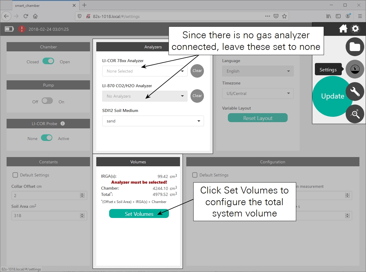
- Enter the system volume.
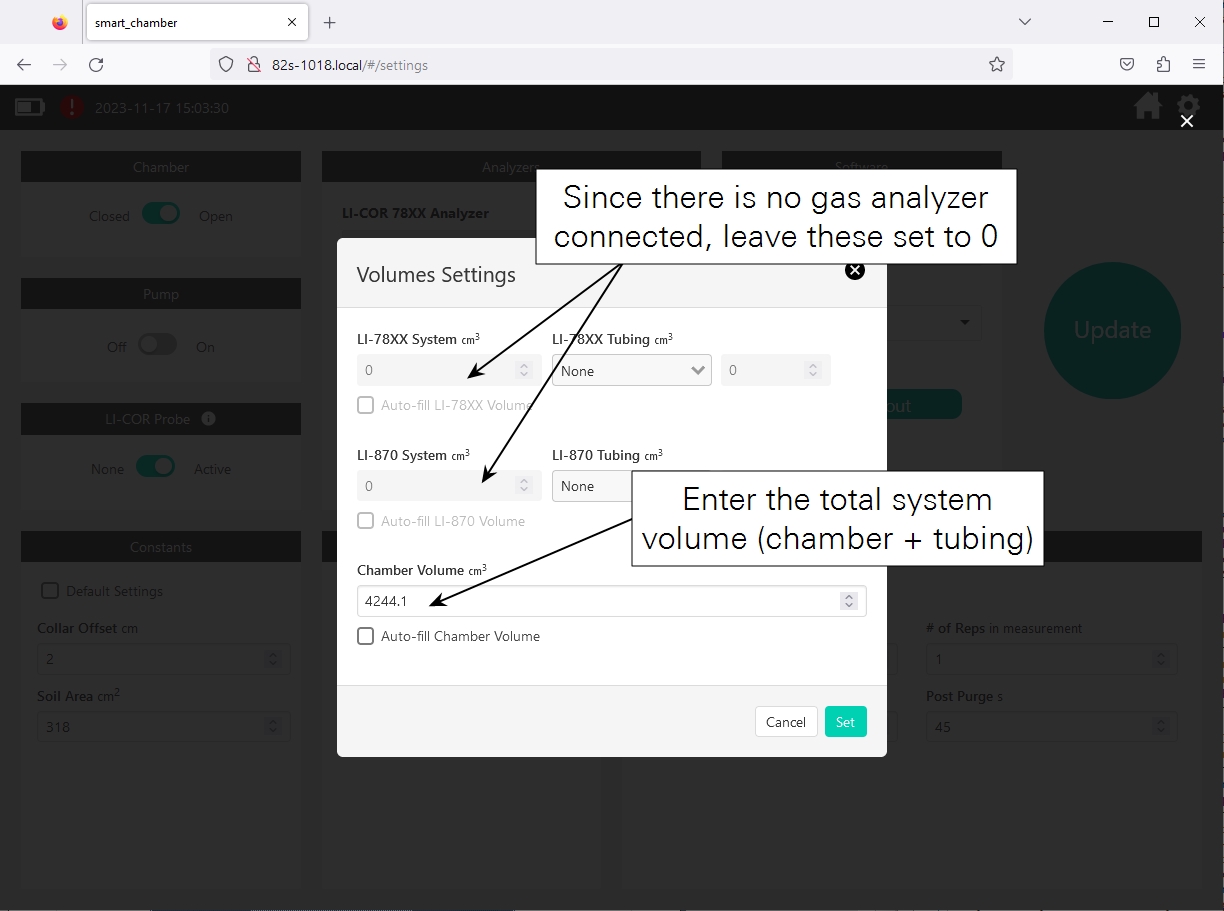
- In the Settings section, do not select an analyzer. Under Volumes, click Set Volumes.
- Volume is calculated by (l × 0.079 cm2) + 4244.1 cm3, where l is the total length of tube (cm) in the sampling kit and 4244.1 cm3 is the chamber volume. For 30 cm of tubing: (30 cm × 0.079 cm2) + 4244.1 = 4246.5 cm3.
- Note that the loss in total system volume from sampling is not significant enough to require a recalculation of system volume for each subsample. The contribution of the T-shaped compression fitting assembly to the total system volume is also negligible.
- Configure the rest of the measurement according to the instructions in Measurement tutorial, and the tap Update, and return to the home screen to start the measurement.
- Place the Smart Chamber and start the repetition.
- With the chamber open and syringe not yet inserted into the septum of the Swagelok fitting, place the chamber on the soil collar and begin the repetition.
- Extract the first sample.
- The first subsample should not be extracted until at least 20 seconds after the chamber closes. After 20 seconds, insert the first gas-tight syringe into the septum, and extract a full sample of air, and cap the syringe after extraction.
- Extract additional samples.
- Repeat the extraction process for the remaining syringes at the intervals determined earlier in this tutorial.
- Finish the Repetition.
- Following the instructions in , complete the measurement cycle. If you will be collecting another set of samples on a new collar, move to that collar and repeat the process (assuming your measurements are programmed correctly). If not, return to your analysis site and analyze the gas according to your preferred method (gas chromatography, mass spectroscopy, etc.)
Data analysis
Depending on the behavior and shape of the time-series data, the rate of change of the trace gas concentration (dC'/dt) inside the chamber can be estimated with either a linear regression or exponential curve fit (see Deriving the flux equation for CO2). If you choose to use an exponential curve fit, it is suggested that you use dC'/dt at t = 0, considering t = 0 as the time when the first trace gas sample was extracted.
After obtaining dC'/dt, the flux (F) is calculated using the following equation:
A‑1

Where W0 is the initial water vapor mole fraction (mmol mol-1), T0 is the initial air temperature (°C). V is total system volume (cm3), P0 is the initial pressure (kPa), S is the soil surface area (cm2), R is the gas constant (8.314 Pa m3 K-1 mol-1). See Soil gas flux measurement theory.
Note: The application note included with your Trace Gas Sampling Kit is based on the LI-8100A, which automatically calculates water vapor and embeds this data in the data files merged with external data in SoilFluxPro. Because the Smart Chamber data files do not contain water vapor data, you must also calculate this for your samples and include these in your data files.
After the Smart Chamber data file is transferred to your computer, the values for variables T0, P0, W0, V, and S can be easily copied or exported through SoilFluxPro Software. In the data files, these variables will be labeled in the columns IV Tcham, IV Pressure, IV H2O, Vtotal, and Area.
If the units for trace gas concentration are μmol mol-1 or ppm, then the final units for flux will be μmol m-2s-1. If the units are nmol mol-1 or ppb, then flux will have the units of nmol m-2s-1.