


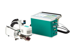
The Start Up tab presents initial information about the instrument and the configuration. Some options are specific to the chamber attached and these are described in detail in the respective sections. Here we describe features of the Start Up tab that are common to all chambers.
Chamber setup
Under Start Up > Chamber Setup, you'll see options for the attached chamber on the left and the chamber details on the right. The form it takes depends upon which chamber is attached:
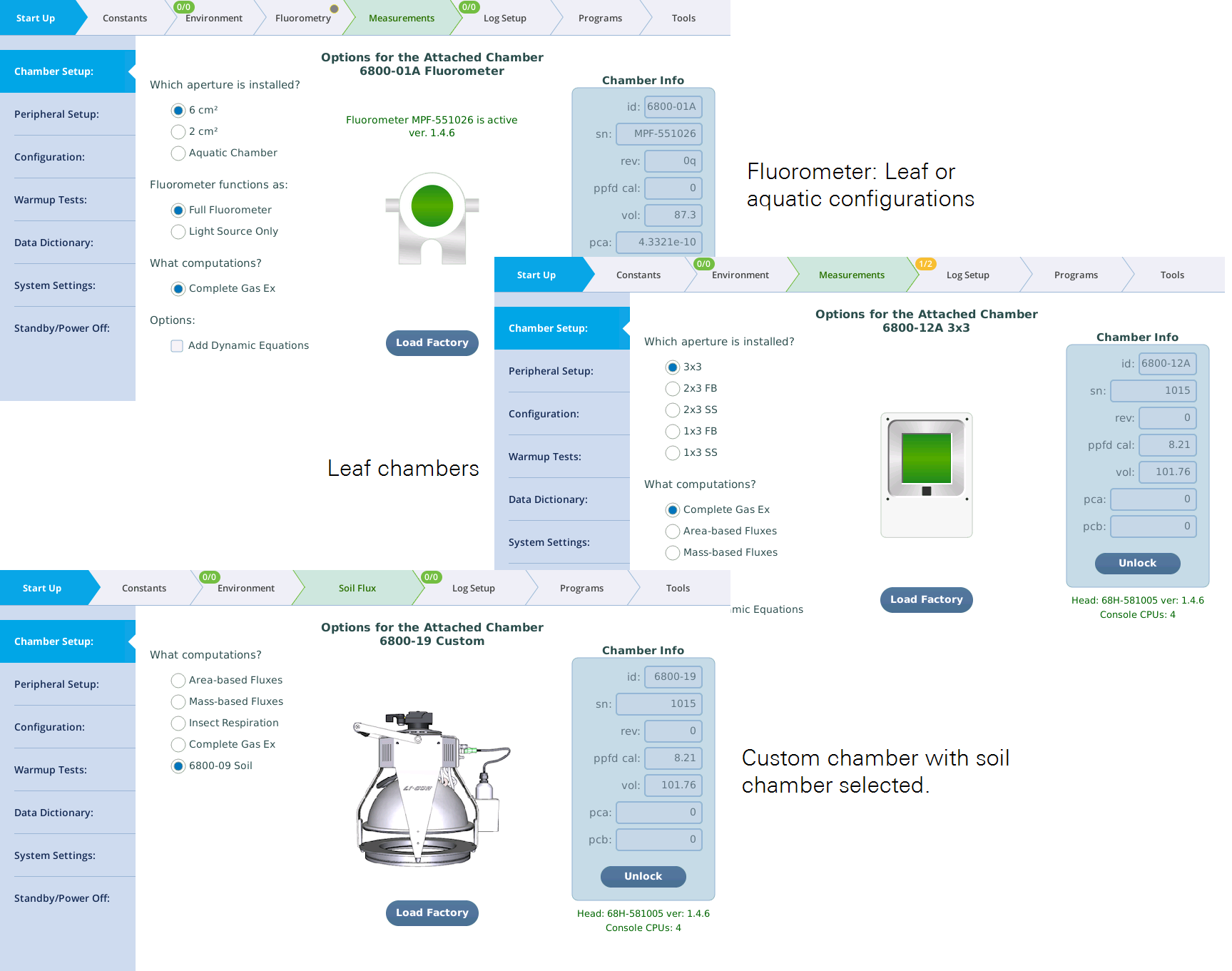
See the following for details that are specific to each configuration.
- Fluorometer software controls.
- Leaf chamber software controls.
- Aquatic chamber software controls.
- Soil chamber software controls.
Note: The controls for this page are disabled when a log file is open.
Any chamber-related calibration values will be automatically populated when you connect a light source. The button labeled Load Factory is a quick way to set the LI-6800 for the factory defaults appropriate for the attached chamber.
What computations?
The Chamber Setup page allows you to select which computations. The options depend upon which chamber is attached. These are Complete Gas Ex, Area-based Fluxes, Mass-based Fluxes, Insect Respiration, 6800-09 Soil, or CO2 Flux with the aquatic chamber.
Note: Toggling between computation options will automatically cause grids and graphs to reset to the appropriate factory default.
Complete gas exchange encompasses photosynthesis A, transpiration E, conductance g, and all of the usual computations that derive from them. Non-fluorometer chambers also provide for just A and E, on a leaf area basis (mol or mol m-2 s-1) or mass basis (mol or mol kg-1 s-1). With mass-based fluxes, the only gas exchange constant (under the Constants tab) is Mass in grams (gm). Area S and stomatal ratio K are not available (Figure 3‑2). The two flux options are the only options available for any chamber without provisions for measuring leaf temperature (e.g., 6800-17).
| Name | Quantity | Units | Description |
|---|---|---|---|
| Area based fluxes | A | µmol m-2 s-1 | CO2 flux |
| E | mol m-2 s-1 | H2O flux | |
| S | cm | Leaf area | |
| Mass based fluxes | A | µmol kg-1 s-1 | CO2 flux |
| E | mol kg-1 s-1 | H2O flux | |
| Mass | gm | Plant mass | |
| Insect respiration | Resp | µg g-1 min-1 | Insect respiration |
| E | mol kg-1 min-1 | Insect "transpiration" | |
| Mass | gm | Insect mass |
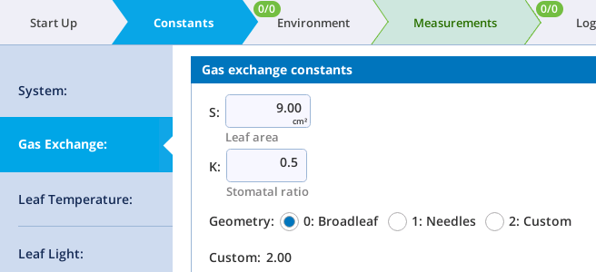
Chamber info
These fields present the information saved in a chamber's EPROM memory. They are programmed at the factory. They can be edited.
- id - The model number will be one of these: 6800-01, 6800-01A, 6800-12, 6800-12A, 6800-13, 6800-17, or 6800-19.
- sn - The serial number should match the number on the chamber label.
- rev - A revision number. Not used currently.
- ppfd cal - The light sensor calibration factor is used for the 6800-12, 6800-12A, and 6800-13 chambers. For the other chambers, this value can be missing or zero.
- vol - The chamber volume (cm3) is used to tune the response time of control loops when controlling the sample CO2 or water vapor. See Table 3‑2.
- pca, pcb - Two coefficients used to correct measured chamber over pressure ΔP (kPa) for the effects of fan speed (rpm) R and flow rate F (µmol s-1). Not all chambers require this. See Table 3‑2 for pca and pcb values.
| Chamber | Serial Number (sn) | Revision (rev) | Calibration Factor (ppfd cal) | Volume (vol) | pca | pcb |
|---|---|---|---|---|---|---|
| 6800-01 Fluorometer | MPF-###### | na | na | 83.6 | 0 | 0 |
| 6800-01A Fluorometer | MPF-###### | na | na | 87.3 | 4.3321E‑10 | 1.0215E‑5 |
| 6800-12 3×3 cm Chamber |
CHM-##### | na | see calibration certificate | 101.8 | 0 | 0 |
| 6800-12A 3×3 cm Chamber |
CHM-##### | na | see calibration certificate | 109 | 2.6520E‑10 | 1.3064E‑5 |
| 6800-13 6×6 cm Chamber |
CHM-##### | na | see calibration certificate | 193.7 | 4.3998E‑11 | 1.4792E‑5 |
| 6800-17 Small Plant Chamber | na | na | na | 193.2 | 0 | 0 |
| 6800-19 Custom Chamber |
na | na | na | ? (~200) | 0 | 0 |
Factory defaults
Tapping the Load Factory button will reset the indicated configuration groups to factory defaults appropriate for the chamber and options you have selected. Here are some examples:
If selected, the EnvLight configuration group implements factory default settings for each currently attached light source. If the attached chamber is compatible with the light source (as in, clear-top 3×3 cm chamber and small light source), the LI-6800 assumes that the light source is attached to the chamber.
In the GasEx group, leaf temperature constants are set for measuring leaf temperature using connector T1. Gas exchange constants are set for Complete Gas Exchange, and leaf area depends on the attached chamber. If the chamber supports apertures, it selects the default aperture.
In the EnvFlow group, the flow rate is set according to the attached chamber.
Peripheral Setup
The Peripheral Setup tab presents power controls for the Accessory connector on the console, the LS connector on the head, and the auxiliary power connector available though the custom chamber adapter. It provides full controls for the USER I/O DB-25 connector on the console.
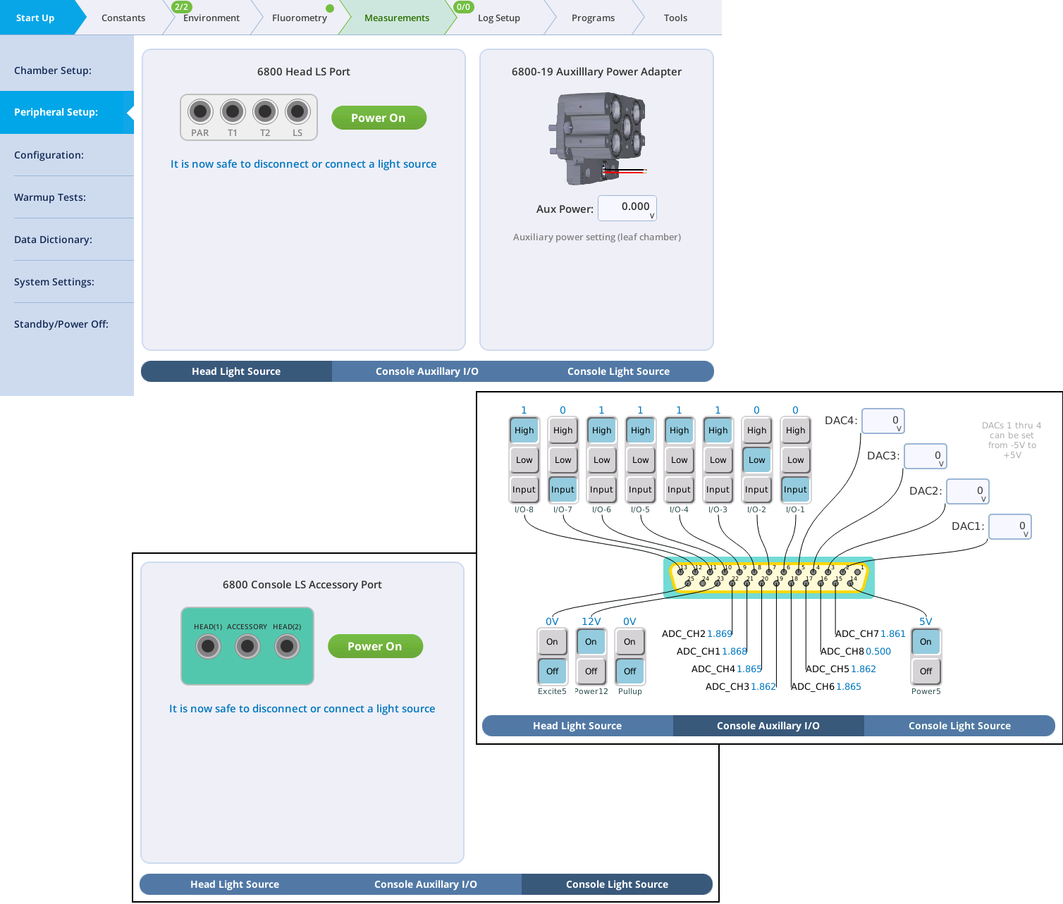
Light sources will be detected automatically on start up and when the light source cable is connected, but you can power them on and off manually.
See the following for more details:
- Head Light Source: See Connecting the small light source or Connecting the large light source.
- Console Auxiliary I/O: See Using auxiliary channels.
- Console Light Source: See Using two light sources simultaneously on the LI-6800.
Configuration
The LI-6800 has a number of features that are user configurable (graphs, CO2 control, fan control, etc.). At power on, most of these features “remember” their previous configuration, and return to it by default. The Configuration tab, however, allows you to save and retrieve collections of configuration settings with just a few taps. Note that when a file is saved, you can specify which configuration items are to be included. When a file is retrieved (loaded), you are presented with a check-box list of the items included in the file, so that you can clear any you don’t wish to implement.
Configuration files are stored in the directory /home/licor/configs. When saving configurations, you can create subdirectories under that directory if desired.
The Configuration tab has three sub-tabs:
-
Load: Load selected configurations from a previously store file.
-
Save: Save a select set of configuration to a file (new or re-used).
-
Extras: This is new feature in version 2.2, and is described in XREFFFFF
Load
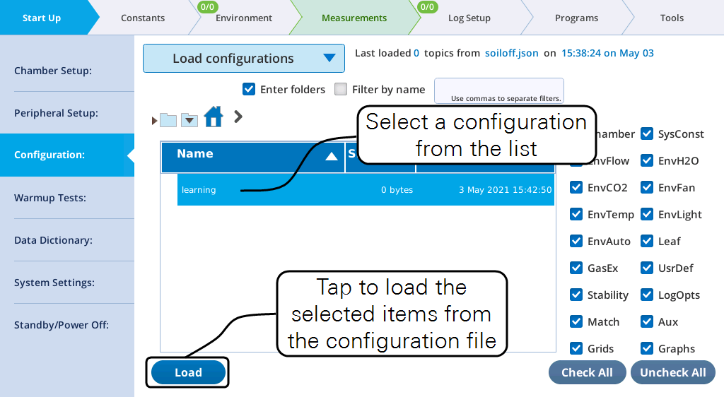
To load a previously stored configuration, pick the file first, then select from the available contents which settings you wish to implement (Figure 3‑3).
Save
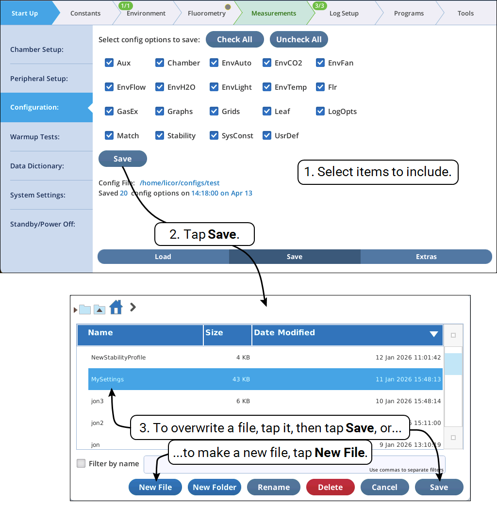
Saving a configuration (Figure 3‑4), begins with selecting the categories to include, then picking the destination file. Note the Save dialog offers some file housekeeping buttons: Rename and Delete. The latter simply moves files to the trash, allowing rash decisions to be undone.
Configuration categories
The user configuration categories are described below. Items with a * are only active for certain configurations. Inactive categories are not available for saving to file. If a file being loaded contains categories that presently inactive, the are ignored.
-
Aux: Settings for the User I/O DB-25 connector of the console (Logging the auxiliary channels).
-
Aquatic*: Aquatic chamber constants (Aquatic Chamber constants). Only active while configured for Aquatic chamber.
-
Chamber: See Chamber setup. Note that this category will be ignored if loaded while a log file is open.
-
Dynamic*: See Dynamic configuration elements. Only active if configured for Dynamic Assimilation Technique.
-
EnvAuto: Settings for all 6 of the Auto Controls (see Auto Controls).
-
EnvCO2: CO2 control.
-
EnvFan: Fan control.
-
EnvFlow: Flow control.
-
EnvH2O: H2O control.
-
EnvLight: Light control.
-
EnvTemp: Temperature control.
-
Flr*: See Measuring chlorophyll a fluorescence. Includes measuring, multiphase, rectangular, induction and dark pulse settings, fluorometer log options, and computational constants). Inactive unless configured for Full Fluorometer (as opposed to Light Source Only).
-
GasEx: Gas Exchange constants (see The Constants tab) and Leaf Temperature constants (see Leaf Light).
-
Graphs: Measurements graphs. See Graphs.
-
Grids: Measurements grids. See Grids.
-
Leaf: Leaf light settings. See Leaf Light.
-
LogOpts: Logging options. See Logging options.
-
Match: Match settings, both point and range. See Matching the IRGAs.
-
Soil*: 6800-09 Soil Chamber. See Measuring soil CO2 flux. Inactive if not configured for this.
-
Stability: Stability criteria. See Stability.
-
SysConst: Averaging time and Oxygen concentration. See The Constants tab.
-
TGA*: Trace Gas Analyzer support, see TGA and User Configurations. Inactive if not configured for this.
-
UsrDef: User defined constants and variables. See User.
User I/O port conflict resolution
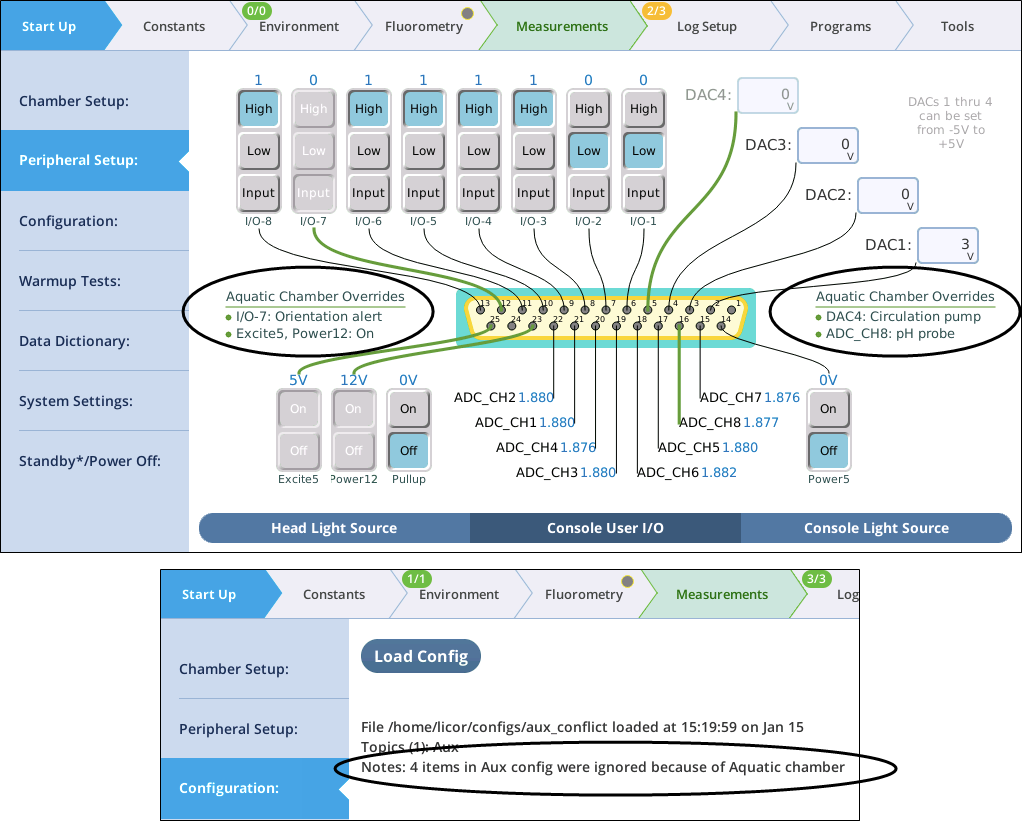
Most of the time, the User I/O DB-25 connector is reserved for the user. But not always. The Aquatic Chamber and TGA support both use some of the pins on that connector. The connectors associated with those accessories will prevent you from physically accessing those pins accidentally. On the software side, the user interface does alert you (e.g., Figure 3‑5) when pins are reserved by modifying the diagram and disabling the affected pins’ controls from direct user interaction. In addition, any Aux settings in a user configuration being loaded are screened to prevent reserved pin settings from changing accidentally as a result of that load.
Extras
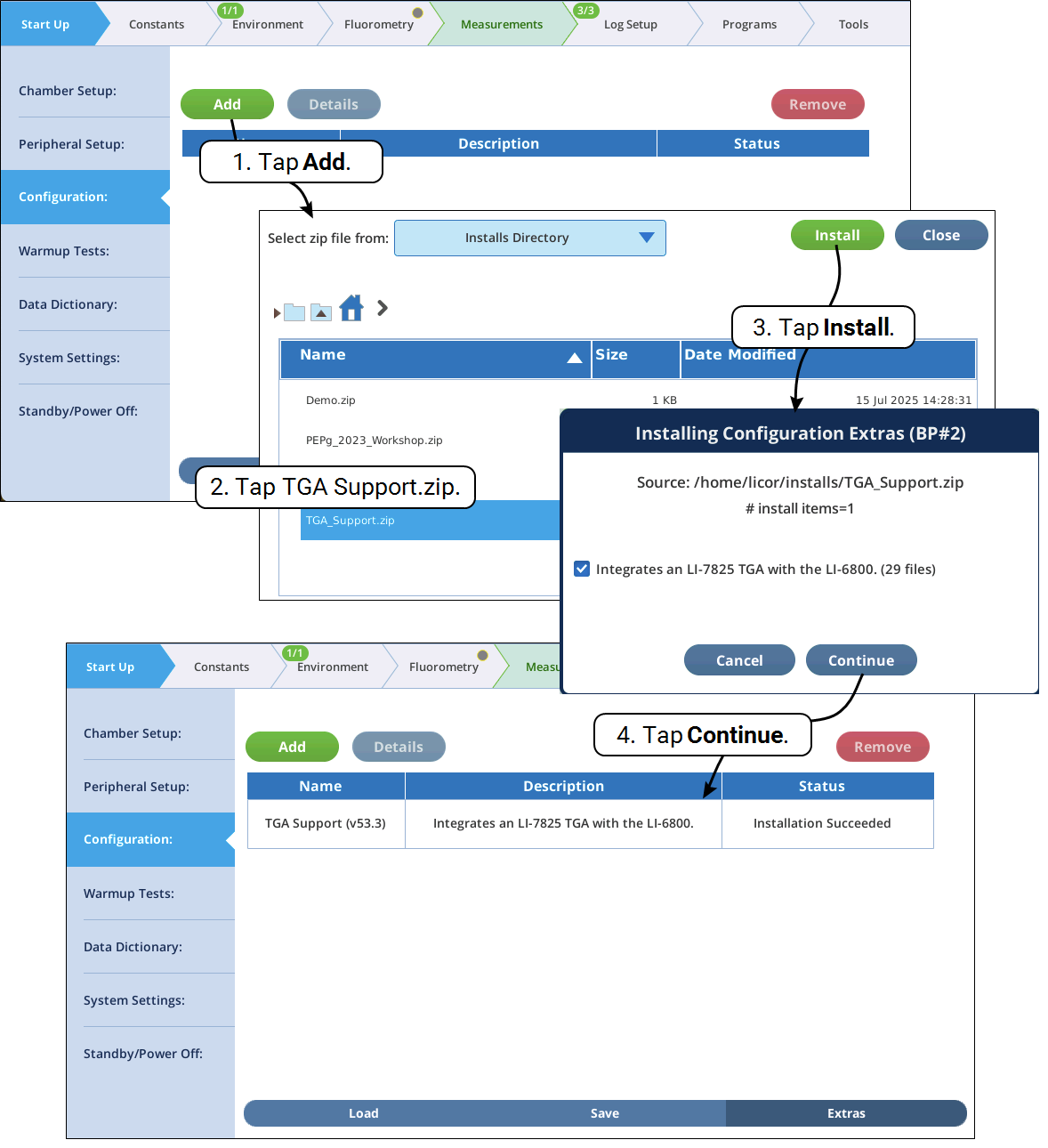
Configuration Extras are new to version 2.2, and represent a method of easily adding (and removing) a collection of files of any sort that are bundled into a zip file that includes directions for where each file needs to be installed. Documentation on using this feature to share files will be forthcoming. Version 2.2 uses this feature to add TGA support (for LI-COR Trace Gas Analyzers), should you care to install it. TGA Support represents a “built-in” config extra, since the zip file is prepared and placed into the install directory (/home/licor/installs) when the system boots up. Figure 3‑6 illustrates how to activate this config extra.
Warmup tests
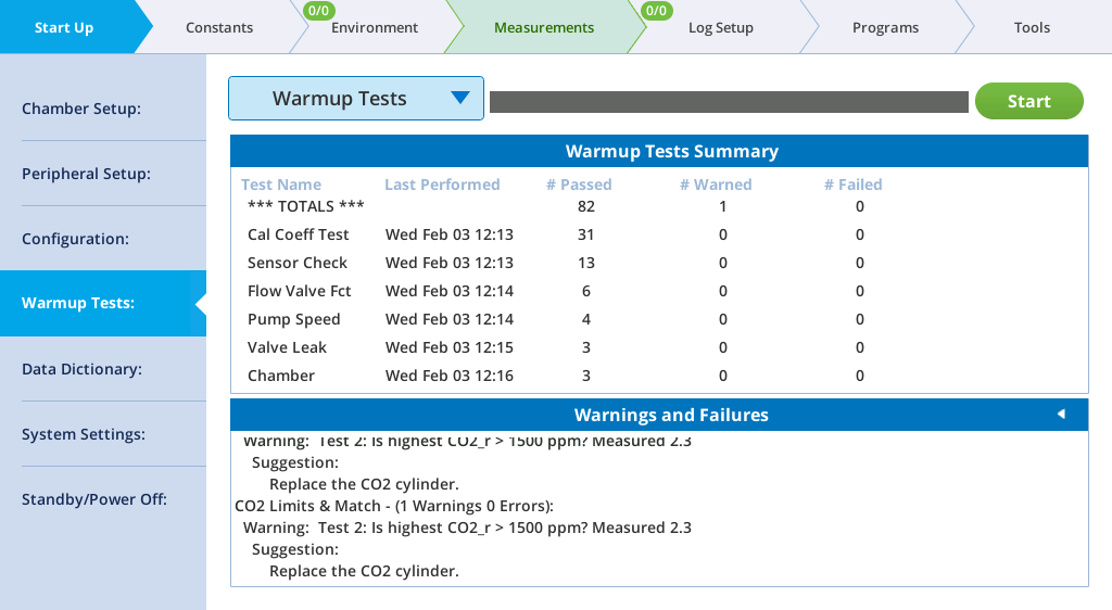
The warmup tests are designed for daily use, to catch errors and faults that might compromise your measurements. If everything passes, you can be reasonably sure (but not guaranteed) that the system is working as expected. Common failures are due to worn out desiccant or an empty CO2 cylinder. Other failures may be simply because a setting or measurement is just outside the expected range, in which case you have to decide if it needs attention or can be ignored.
The tests are a convenient way to diagnose issues with the instrument. There are groups of tests: Warmup Tests, Controller Tests, Fluorometer Tests, and Tech Tests. You can run tests as a group or individually. For details on the tests, see Warmup tests.
Data dictionary
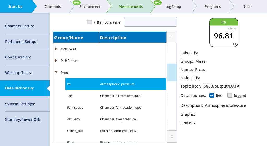
The Data Dictionary shows terms that are used by the LI-6800. Terms are grouped, as described in Summary of symbols. For each variable, it will show the Label, Group, Name, Units, Description, Data sources, and the value for that variable. By toggling live or logged, you can see the current value or the last value logged.
System settings
The System Settings tab is where you configure basic instrument settings, such as display brightness and volume level.
You can set the Autofill behavior for the number pad and keyboard. So, if you're annoyed by the numbers that automatically populate the number pad entry, you can change the setting here. Or, if you would prefer that the number pad always display the current setting when opened, change it here too.
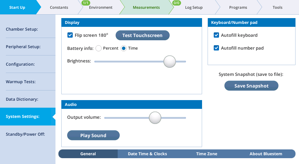
Under General, you can change the Display settings: Flip the screen 180° so your coworker on the other side of the table can see it, launch the touchscreen test, change the battery from percent remaining to time remaining (an estimate), and adjust the brightness.
The Audio setting allows you to alter the audio level and check it by tapping Play Sound.
Keyboard/Number pad settings are independent: you can alter the Autofill behavior to suit your preferences.
The Save Snapshot button presents the option to take a record a file that shows the state of the system at that moment. This is helpful for troubleshooting and diagnostic purposes if the system seems weird — it is a quick way to capture some strange special moment. See Snapshots for details about the snapshot file.
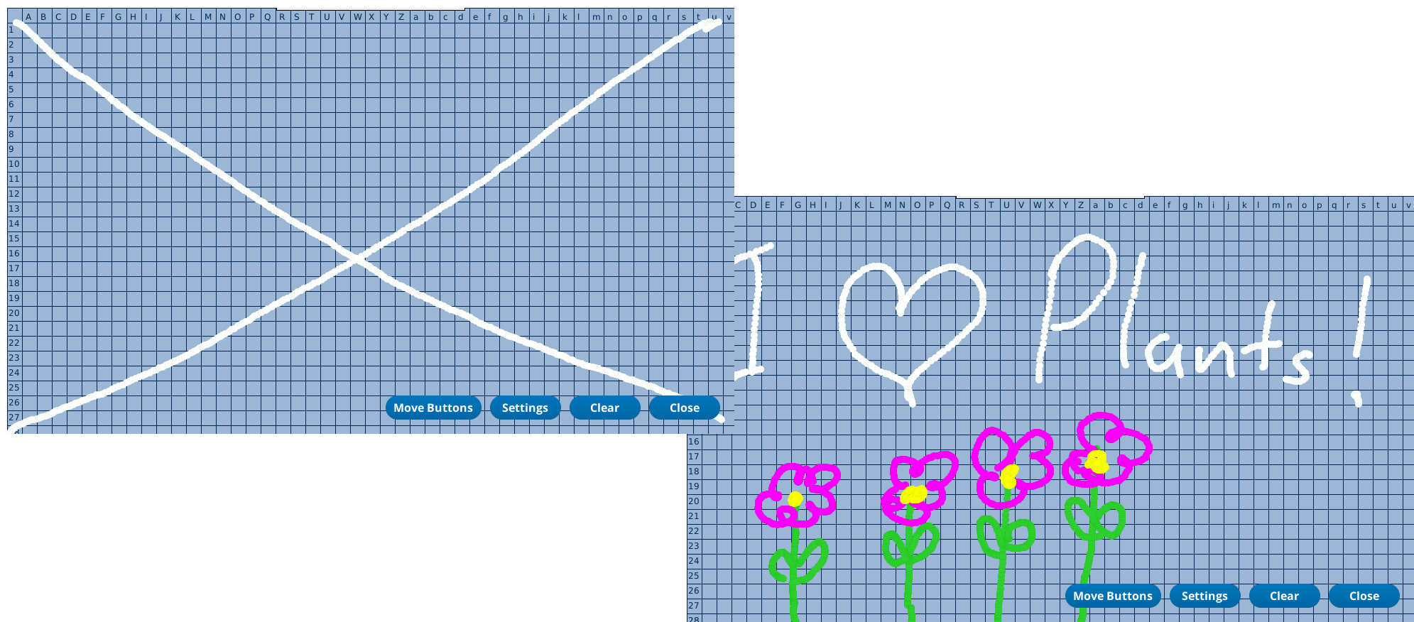
If you suspect a "dead" region on the touchscreen, you can use the Test Touchscreen button to test the screen. Drawing a big X from corner to corner will quickly find any inactive columns or rows. A dead band will be a vertical or horizontal band all the way across the display in which you cannot make a mark.
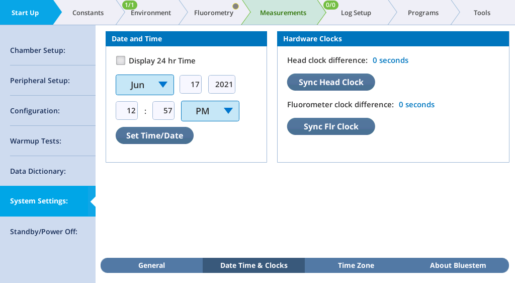
The Date, Time & Clocks tab can be set by a user, but the setting will automatically reset to the network time when the instrument is connected to a local area network or the internet. The changes to the time zone, however, will be stored. You can check for any discrepancies between the clock in the console and head, and correct it by tapping Sync Head Clock and Sync Flr Clock. (a fluorometer must be connected for the clock to be synced).
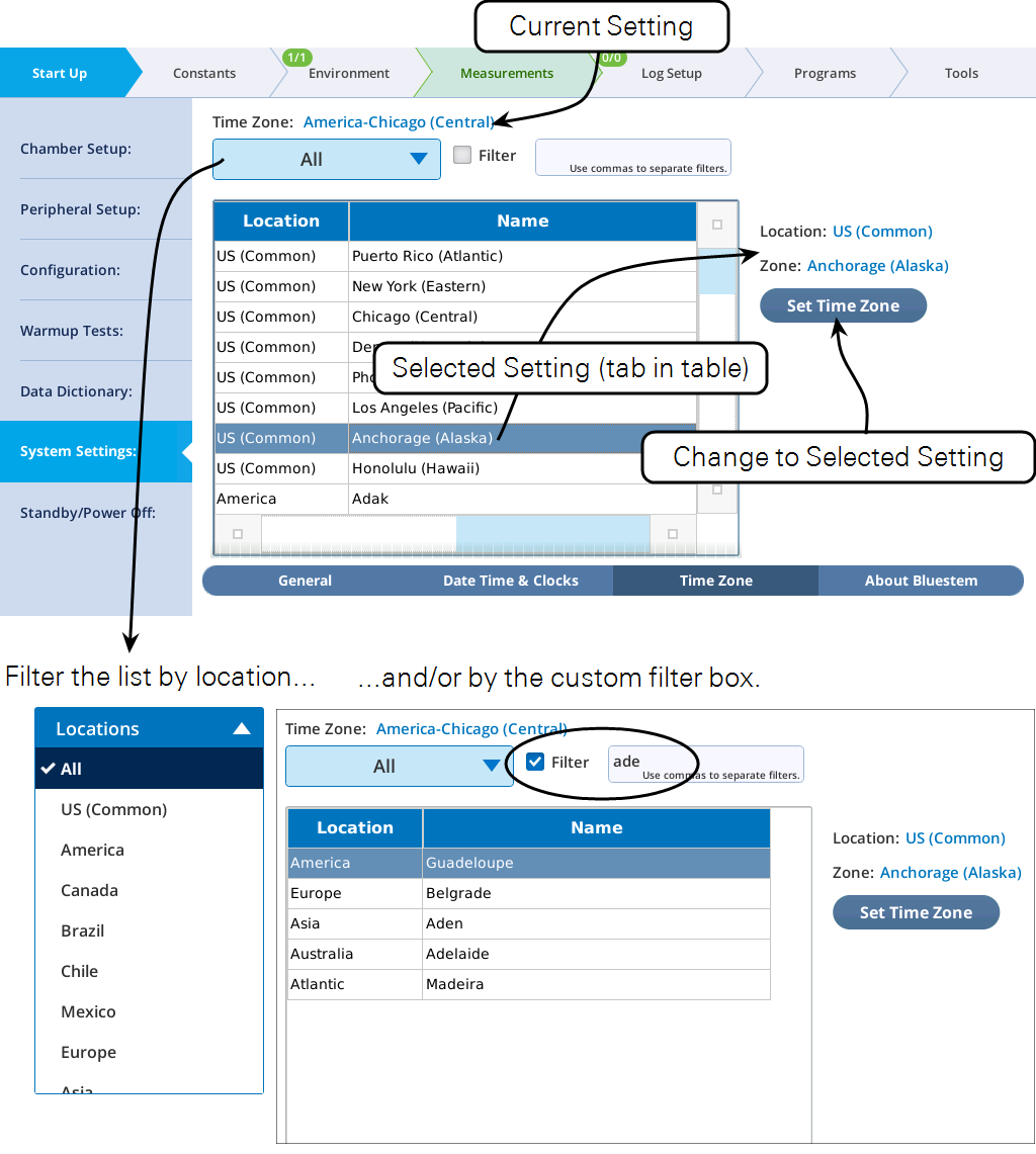
The Time Zone option allows you to apply an offset to the system time by selecting a zone.
About Bluestem tells you about the operating system on the instrument and other software licensing information. You may need to view this in consultation with technical support.
Standby and power off
When you're in the middle of a field day, or if you just got everything going and now it is time to take a break, you may want to keep all the current settings, but not consume the chemicals and battery power while you take a tea break. There are two settings for this: Standby (All controls off) and Sleep (Controls and gas analyzer off).
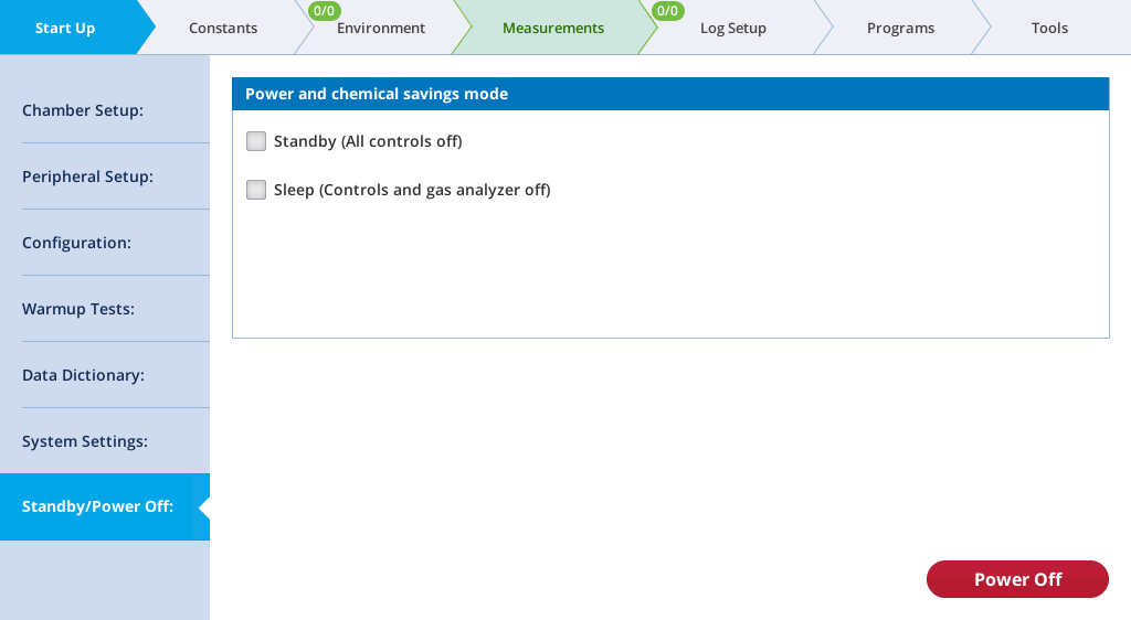
Standby (All controls off), formerly called Conserve Chemicals, will shut down all environmental controls and light sources. Disabling this setting will bring them back to their previous values. When disabled, turning on Flow, H2O, CO2, Fan, or Temperature, will end Standby mode.
Sleep (Controls and gas analyzer off), formerly Conserve Power and Chemicals, will shut down all power-consuming components in the head, including IRGAs, temperature controls, and fans. Data values will stop updating.