Maintenance
The LI-710 requires little maintenance under normal circumstances. However, some routine attention will ensure that the instrument keeps running well over the long term, and will help you get better, more complete measurements.
Updating firmware
The IoE Module and any connected device must have compatible firmware. We recommend reinitializing the sensors after applying a firmware update. By reinitializing, the devices will request the most current configuration and operating information from LI-COR Cloud, ensuring that the stack of devices and software are all compatible.
LI-710 firmware
Firmware updates are carried out over the internal USB connector. To update the firmware:
- Download the firmware to a directory on your computer.
- Firmware updates are available here.
- Power off the instrument by removing the power cable at the connector.
- Remove the electronics cover.
- Do not apply torque to the transducer housings or arms.
-
Warning: Potentially hazardous voltages may be present when the cover is removed and the instrument is powered on. Do not touch any internal components or surfaces while the external cover is removed and the instrument is powered on.
- Connect a user-supplied USB-micro cable between your computer and the connector on the circuit board.

- Connect the power cable to power the instrument ON.
- If the instrument is powered on while a USB cable is connected, it will mount a directory to your computer called FW_UPDATE. Open the directory if it doesn't open automatically.
- Copy the file you downloaded into the FW_UPDATE directory.
- When the LI-710 "notices" the new file, it will automatically close the window and initiate the update. You may see a message indicating that the update was successful.
- Disconnect the power and USB cables and install the electronics cover.
- Restart the LI-710 after updating the firmware.
- Be sure the USB cable is not connected when restarting for normal operation.
IoE Module firmware
Leave sensors connected to the IoE Module when updating the IoE Module firmware.
IoE Module firmware updates are loaded from a computer to the IoE Module using the USB port. To apply the update:
-
Download the file to your computer.
Firmware files are available from Firmware Downloads. The file name is
cwcfw_1.2.0.ioe_pkgor something similar. -
Power off the IoE Module.
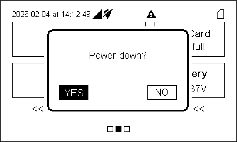
Press the power button (
) and then select Yes to power off the device.
-
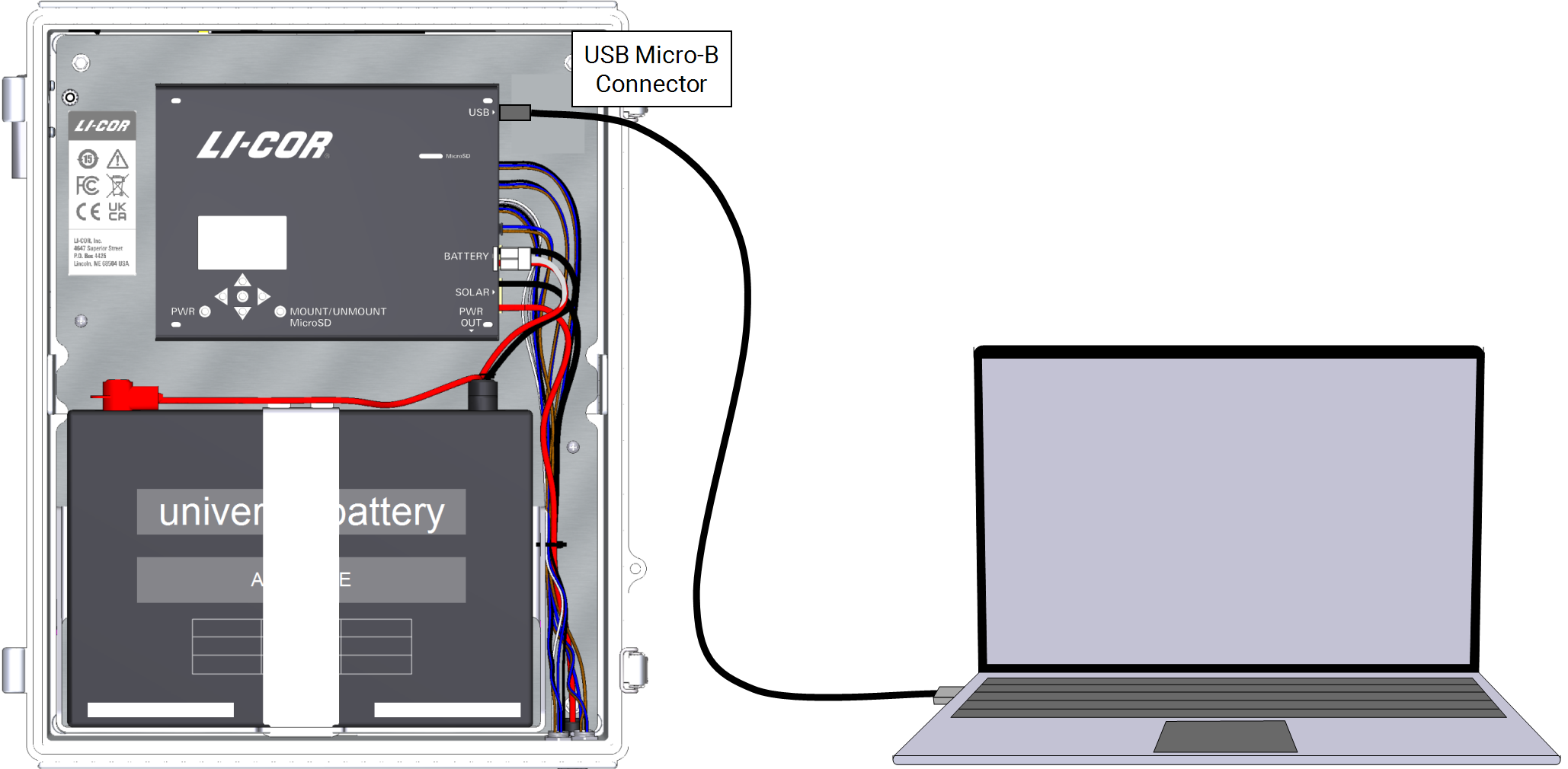
Connect a USB cable between the module and your computer.
The USB connector is labeled in the IoE Module. It accepts a USB Micro-B connector.
-
Power on the IoE Module.
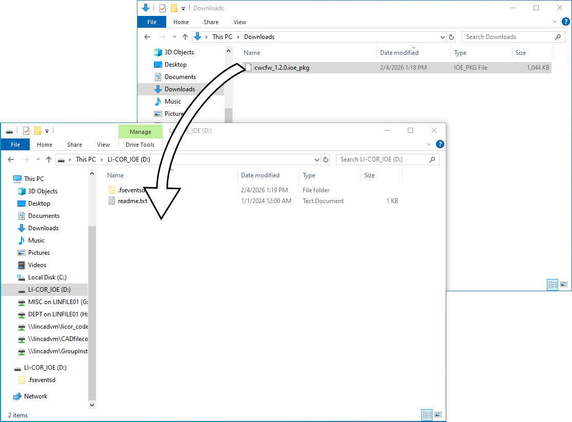
It will start in update mode and appear as a USB drive on your computer called LI-COR_IOE.
-
Drag the file or copy and paste the file to the folder.
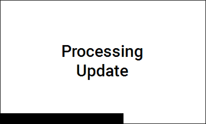
The IoE Module will apply the update. Progress is shown on the display.
-
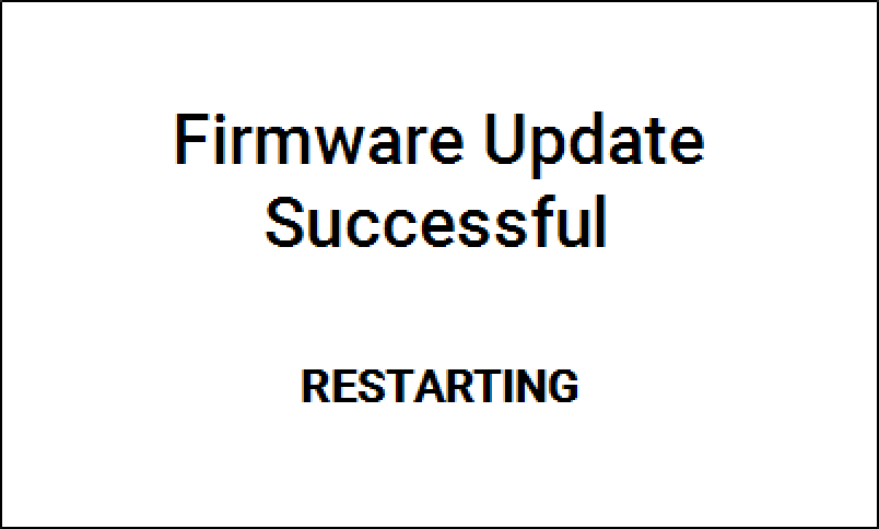
Watch as the IoE Module restarts.
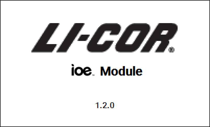
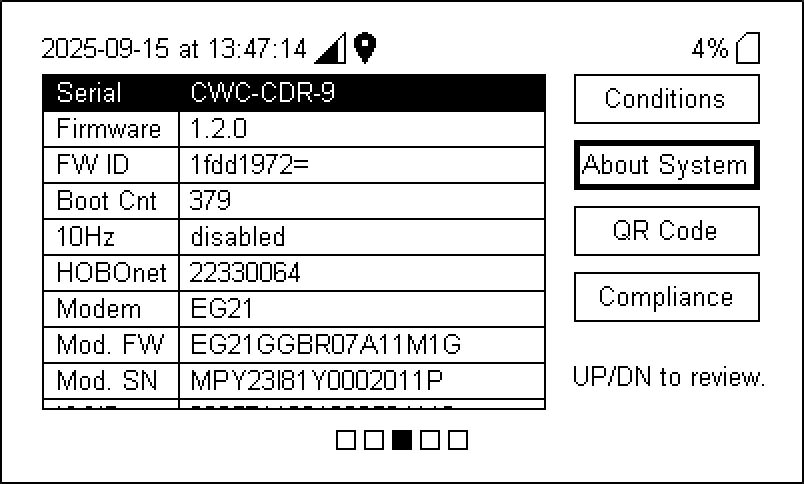
The initialization screen displays the firmware version briefly before advancing to the home screen.
-
Disconnect the USB cable.
To check the version number, press left once (

Reinitialize after firmware updates
If you have updated the LI-710 firmware, be sure to apply the latest device configurations. This is accomplished by deleting the LI-710 and adding it again, which ensures that the IoE Module has acquired the compatible configuration file from LI-COR Cloud. Follow these steps:
-
Enter the Device Setup screen and select the device to remove.
-
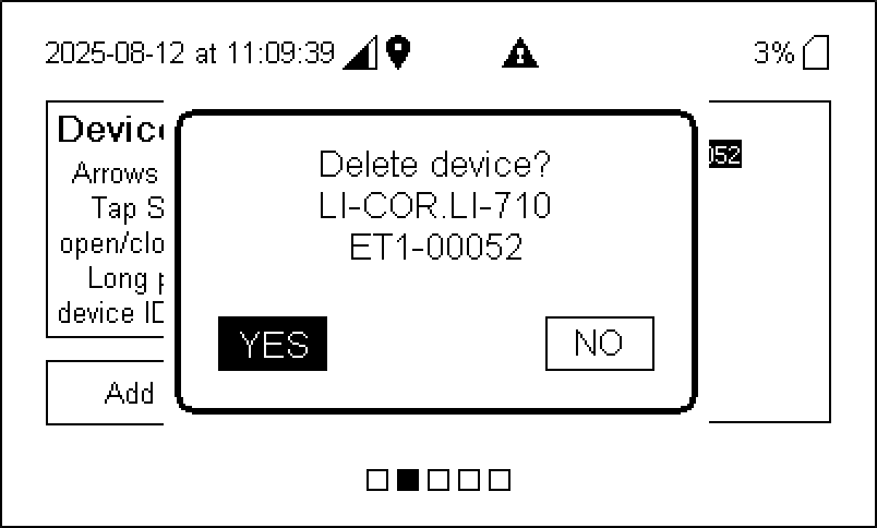
Long-press the Select button (
) until prompted:
-
Highlight YES and then press Select (
).
-
Save the configuration.
Press Right (
) once to open the prompt, then press Select (
) to save the changes. You MUST save changes for the settings to be applied.
-
Follow the steps in Initial setup to reconfigure the sensor.
LI-710 Evapotranspiration Sensor
Basic sensor checkup
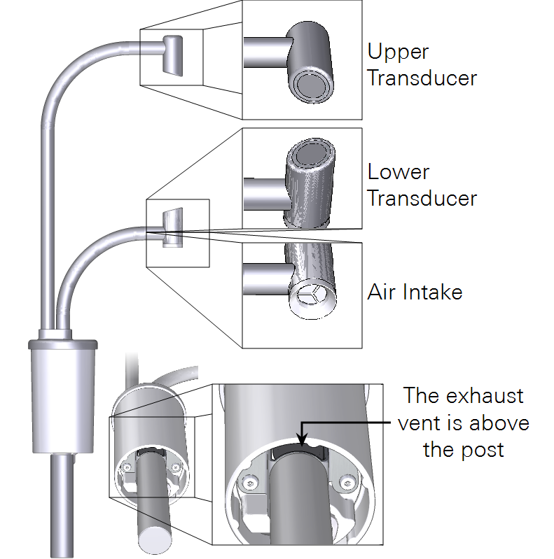
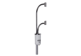
You can conduct a basic check just by looking at the LI-710.
- Check the transducers to be sure they are not covered in bird droppings or dirt. Clean them with a moist cloth and mild detergent if necessary.
- Check the air intake - look for visible obstructions or anything that might interfere with air flow and remove it. If the filter is dirty, replace it (see Replacing the intake filter).
- Inspect the exhaust vent - look for insect colonies or nests. Clear anything that might obstruct the air flow (see Accessing the outlet vent).
Replacing the intake filter
The air intake filter should be replaced approximately once every two or three months, typically. In some conditions, the filter will not need to be replaced as often. In dusty conditions, it may need to be replaced more often.
Low flow rate or high drive voltage may indicate the filter is due for replacement. You can replace the filter and filter O-ring with new ones from the spares kit. This procedure describes how to replace the filter.
| Description | Part Number |
|---|---|
| Filter Replacement Kit | 9971-015 |
| Filter Pack (5) | 6571-002 |
| O-ring Pack (5) | 192-19986 |
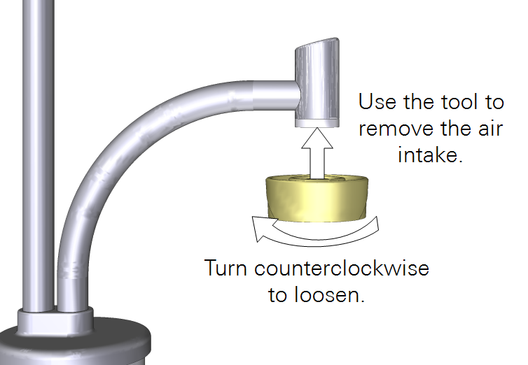
Caution: Do not use a pliers or other metal tools on the air intake! Doing so may deform the parts or alter the alignment of transducers. Instead, use the plastic air intake tool that is included in the spares kit (part number 6371-021).
The intake filter is on the bottom of the lower transducer housing.
- Power off the LI-710 - disconnect the cable.
- Align the intake removal tool with the keys on the air intake and turn it counterclockwise.
- Caution: Do not apply torque to the transducer housings. Doing so can affect the alignment and damage the sensor.
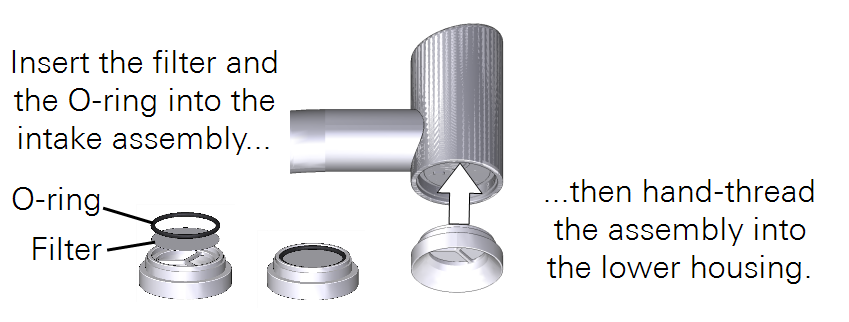
- Once it is loosened, you can remove the air intake with your fingers. Be sure that both the filter and O-ring come out when the intake is removed.
- Install a new filter and O-ring from the spares kit.
- Insert the filter into the air intake, followed by the O-ring.
- Install the air intake.
- Do not cross-thread the air intake. Start tightening the intake with your fingers. Finish tightening it with the tool until it hits a hard stop - around 2 turns clockwise.
Filter replacement is complete.
Replacing the pump and O-rings
The pump inside the LI-710 has a limited life and will need to be replaced periodically. One replacement pump is included with the instrument spares. Additional pump replacement kits are available for purchase. This procedure describes how to replace the pump.
| Description | Part Number |
|---|---|
| Pump Replacement Kit | 9971-016 |
| Pump (1) | 286-17946 |
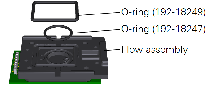
| Pump O-ring 29×2 mm VITON 75 (1) | 192-18249 |
| Pump O-ring 16×1.5 mm VITON 75 (1) | 192-18247 |
| M3×0.5-20 Installation Screws (4) | 151-18159 |
| 2.5 mm Hex Key (1) | 611-20555 |
- Power off the LI-710 - disconnect the cable.
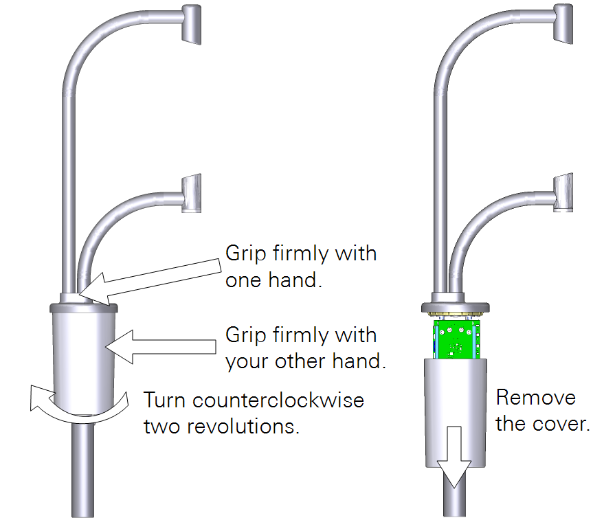
- Remove the electronics cover.
- Do not apply torque to the transducer housings or arms.
- Set the LI-710 on a workbench with the arms pointing away from you.
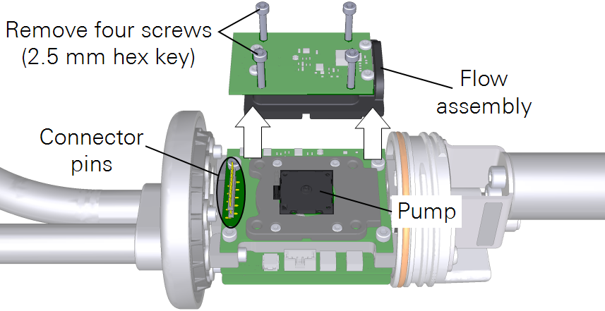
- Remove the flow assembly.
- Remove the four screws using the 2.5 mm hex key from the spares kit. Pull straight up while gently wiggling the flow assembly to separate it from the connector pins.
- Important: Do not bend the connector pins or remove any other screws.
- Remove the old pump.
- It will come out easily; use a tweezers if needed.
- Inspect the O-rings - if you see cracks or damage, replace them.
- Extra O-rings are in the spares kit. Both O-rings press into place in the flow assembly.
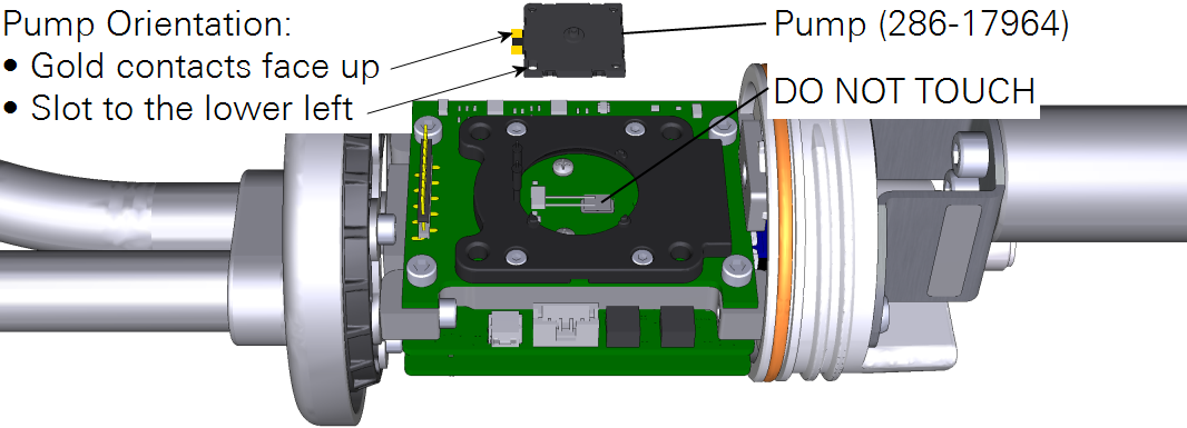
- Set the new pump in place.
- Important: Handle the pump by its corners. Do not touch the diaphragm or the board-mounted components under the pump. Align the new pump (part number 286-17964) with the keys.
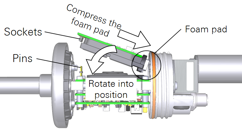
- Install the flow assembly.
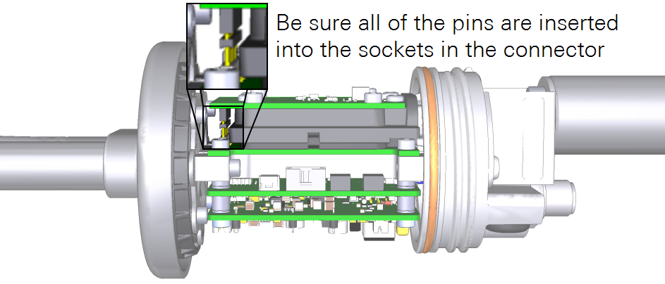
- Compress the foam pad and then rotate the flow assembly into place. Be especially careful with the connector - ensure that each pin meets the corresponding socket, then press them together.
- Install the four screws that secure the flow assembly.
- Extra screws are in the spares kit (part number 151-18159).
- Install the cover.
- Tighten the cover until it hits a stop and will no longer turn - about two revolutions.
The pump replacement is complete.
Accessing the outlet vent
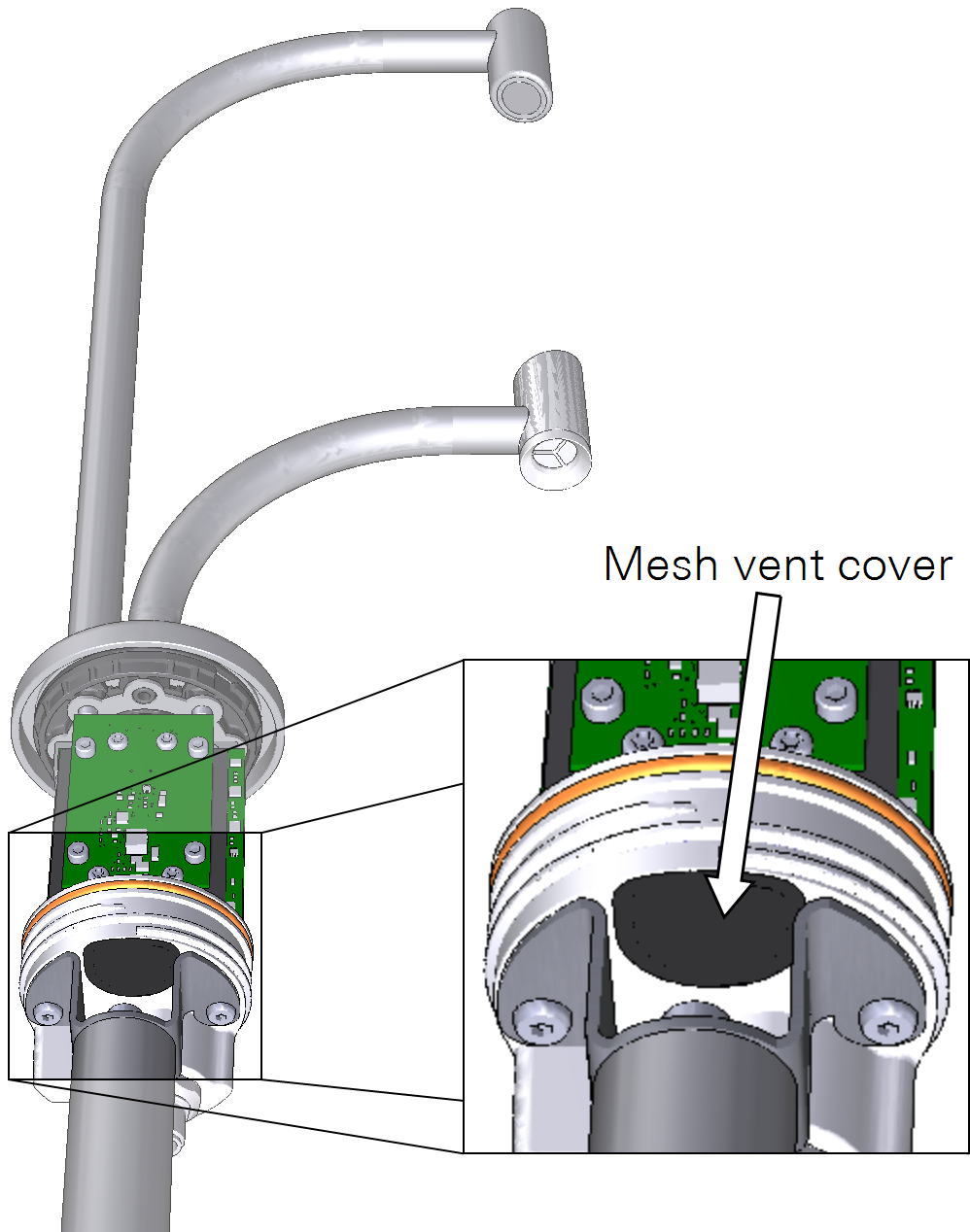
Disconnect the power cable and then remove the cover to access the exhaust vent.

The vent is between the post and the sensor body. Do not remove the post or loosen the screws that secure it. Use a cotton swab to clear debris from the vent. Do not damage the vent screen.
IoE Module
The IoE Module should provide maintenance-free operation, typically. It has no user-serviceable parts inside besides the main battery and clock battery. If you encounter problems, contact LI-COR or your distributor for assistance. Some simple maintenance procedures may be needed when moving the IoE Module or when placing it into storage.
Disconnecting the solar panel
Read and follow all safety instructions provided with the solar panel. Do not disconnect the panel while it is under load. Cover the solar cells with a blanket or invert it so the cells are away from the sun to reduce the voltage output. Then disconnect the cables from the panel.
Replacing the Micro SD card
The Micro SD card reader supports the FAT32 and ExFAT. Any properly formatted card will work, so long as it has space for files. Other files can be on the card, but they take away storage space that would otherwise be available for data files. You can swap the card while the device is powered off, or use the mount/unmout button to swap the SD card while the device is powered on.
Removing the main battery
Power off the device. Hot swapping is not supported, so be sure to shut down the device before changing the power configuration.
Warning: The battery can explode, start a fire, or cause severe burns if the terminals are shorted together. Exercise extreme care when handling the battery. Use insulated tools when practical.
Caution: Cover the solar panel before disconnecting cables. Remove the solar panel power cables before disconnecting the battery cables. When disconnecting the battery, start with the black cable to reduce the risk of shorting the circuit.
-
Power off the device (press the power button, then select YES).
-
Cover or invert the panel to reduce its output, then disconnect one or both solar panel cables.
-
Remove the black cable from the battery post.
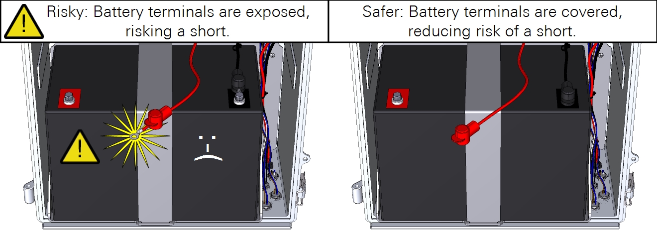
Remove the black one first to reduce the risk of shorting the circuit. Dangling cables may contact metal parts, causing problems. Avoid the problems by covering the contacts with the plastic covers to reduce risk of short.
-
After disconnecting a cable, slide the red and black covers over the metal contacts to reduce risk of a shorted circuit.
Replacing the coin-cell battery
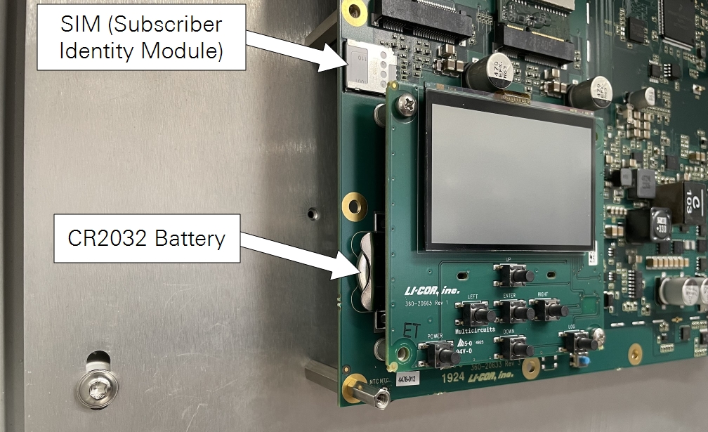
A CR2032 battery is installed on the circuit board. This battery maintains the clock when power is off. If the IoE Module is unable to keep time while powered off, this battery may need to be replaced.
Caution: This procedure exposes the circuit boards of the instrument, which puts them at risk of electrostatic discharge (ESD). Work on an anti-static mat and wear an ESD wrist strap while performing this procedure.
To remove it:
-
Power off the IoE Module and disconnect the power supply and battery.
-
Remove the circuit board cover.
The battery is behind the display circuit board on the lower left side of the main board (Figure 7‑3).
-
Dislodge it with a non-conductive tool, such as a toothpick or stiff plastic coffee stirrer.
-
Replace the battery, then reinstall the cover.
Replacing the Subscriber Identity Module (SIM)
Note: Do not provide your own SIM. Contact LI-COR or your distributor if you need to replace the SIM.
The SIM is behind the circuit board cover (Figure 7‑3). To replace it, power off the device, remove the cover, slide the card out of the slot, and install the new one. After powering on the IoE Module, it will connect with the network automatically if the card is valid and the device has a cellular signal.
Caution: This procedure exposes the circuit boards of the instrument, which puts them at risk of electrostatic discharge (ESD). Work on an anti-static mat and wear an ESD wrist strap while performing this procedure.
