Deploying the LI-720
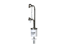
The LI-720 is designed for easy installation with the LI-COR IoE module and other meteorological stations. It uses a single cable for power and communications (SDI-12 and RS-232 serial protocols). Remove the caps that cover the transducers, gas analyzer, PPFD sensor before powering on the instrument (see Figure 3‑1).

Caution: Keep the LI-720 powered off when handling it and installing it. Impacts and collisions – especially when it is powered on – may affect the calibration.
Deployment considerations
Be mindful of these considerations to ensure that the data you collect accomplishes your measurement goals.
Distance from surrounding elements
To ensure that the LI-720 measures a representative area-of-interest, install it above or as far as possible from large obstructions that affect the flow of wind, such as buildings or large solitary trees. Small elements, such as instruments on a weather station, are not problematic, allow clearance of at least two (2) meters, if possible.
Caution: If deploying the LI-720 near other LI-720s, LI-710s, or sonic anemometers, allow at least two (2) meters of clearance to prevent ultrasonic interference. If deploying the LI-720 near a radio antenna, position the antenna >2 meters away from the LI-720 to reduce the risk of electromagnetic interference.
Measurement area
Measurements from the LI-720 represent an area immediately surrounding the sensor. Therefore, you should install the sensor in the middle of the area-of-interest. Large open areas are ideal. For crops and grasslands, the middle of the field is ideal.

If you are unsure where to install the sensor, put it in the middle of the area you want to measure. If you have to choose a side, choose the side that is downwind of the prevailing wind over the area-of-interest (see Figure 3‑3).

Height above the canopy
The area represented in measurements from the LI-720 will depend on its height above the plant canopy. The LI-720 should be installed at least 2 meters above the canopy. At a 2-meter mounting height, the fetch is assumed to be a 100 to 200 meter radius around the LI-720 (see Figure 3‑4). All landscape elements within this range can contribute to the carbon dioxide flux measurement.
Over fast-growing canopies, such as soybeans, sorghum (milo), wheat, flax, rice, maize (corn), vegetables, and cotton, install the LI-720 at 3.5 to 5 meters above the surface before germination for a fetch up to 350 to 500 meters. As the crop grows, the distance between the canopy and sensor will become smaller, and so will the fetch. This is an ideal measurement scenario - the area measured represents the area-of-interest for the entire growing season. Alternatively, you can raise the height of the LI-720 over the growing season to maintain a consistent measurement height.


Over orchards and woodlands, which are characterized by partial to full canopy closure, the LI-720 should be at least 2 or 3 meters above the top of the canopy.

Slope and tilt
The LI-720 should have a vertical orientation. Both pitch and roll are reported by the sensor, but you can use the level application on a mobile phone to confirm that the sensor is vertical.

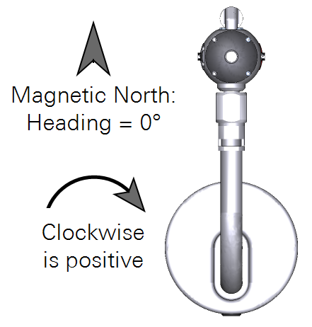
North offset
The LI-720 has a built-in magnetometer that reports a heading of 0° when the sensor is oriented toward magnetic north (not corrected for declination). Headings are positive clockwise, reported as heading in the dataset (see Table 6‑1).
Note: Magnetometers are sensitive to electromagnetic interference from magnetic materials and electrical equipment. If the reported heading seems implausible, move the sensor so it is far from interfering equipment. If there is risk of interference at the site, you can override the measured value with a user-entered value (see Entering site metadata).
Mounting the LI-720
The LI-720 mounts readily to the IoE Module or weather stations and other equipment. For all of the following, tighten the pins against the post using a 5/32" or 4 mm hex key.
Carbon Node: IoE Module adapter
For applications with the IoE Module and Carbon Node, install the LI-720 in the adapter (part number 98512-081). Connect the power/data cable to the LI-720 before installing it in the adapter.


Horizontal cross bar
The LI-720 can be attached to a standard ¾" crossover fitting or any other fitting with a 1" opening. Suitable crossover fittings (¾" × 1") are available from LI-COR (part number 259-13276).


Tighten set screws with a 5/32" or 4 mm hex key to 22 N-m (16 ft-lbs). If no torque wrench is available, tighten each set screw until it contacts the pipe, then ¼ turn more.
Vertical mast
For a stand-alone installation, the LI-720 can be attached to a T-post and vertical mast, like a piece of pipe. The LI-720 can attach to a pipe using a swivel mount (Figure 3‑10).
If you are using a T-post in soft or saturated soils, check the installation regularly to ensure that the post does not shift over time. Use guy wires for additional stability.


Tighten set screws with a 5/32" or 4 mm hex key to 22 N-m (16 ft-lbs). If no torque wrench is available, tighten each set screw until it contacts the pipe, then ¼ turn more.