Connecting to and configuring the system
Connecting to the biomet system
The Blueprint Utility is software to configure the data acquisition system. Go to licor.com/ec-software for the latest version and install it on your computer.
Here describe how to connect with DAqMs and a DRM, enter sensor calibration information for sensors and send a configuration to the system. Additional information is provided inside the app (click Help) and in Blueprint Utility software reference.
Connecting Ethernet cables
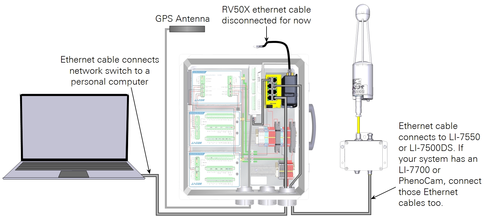
Connect the DRM and all DAqMs together before sending a configuration. You will communicate with the DRM and DAqMs through the SmartFlux 2 or 3 System. The LI-7500DS or LI-7550 (for the LI-7500A/RS or LI-7200/RS) is required to complete the system, but is not required to configure the biomet system. Connect the computer to a vacant port on the network switch.
Power on the system
Move the breaker to the ON position to power on the DRM, DAqM, SmartFlux System, and Network Switch. Allow several minutes for the system to start up.
Launch the Blueprint Utility and load a program
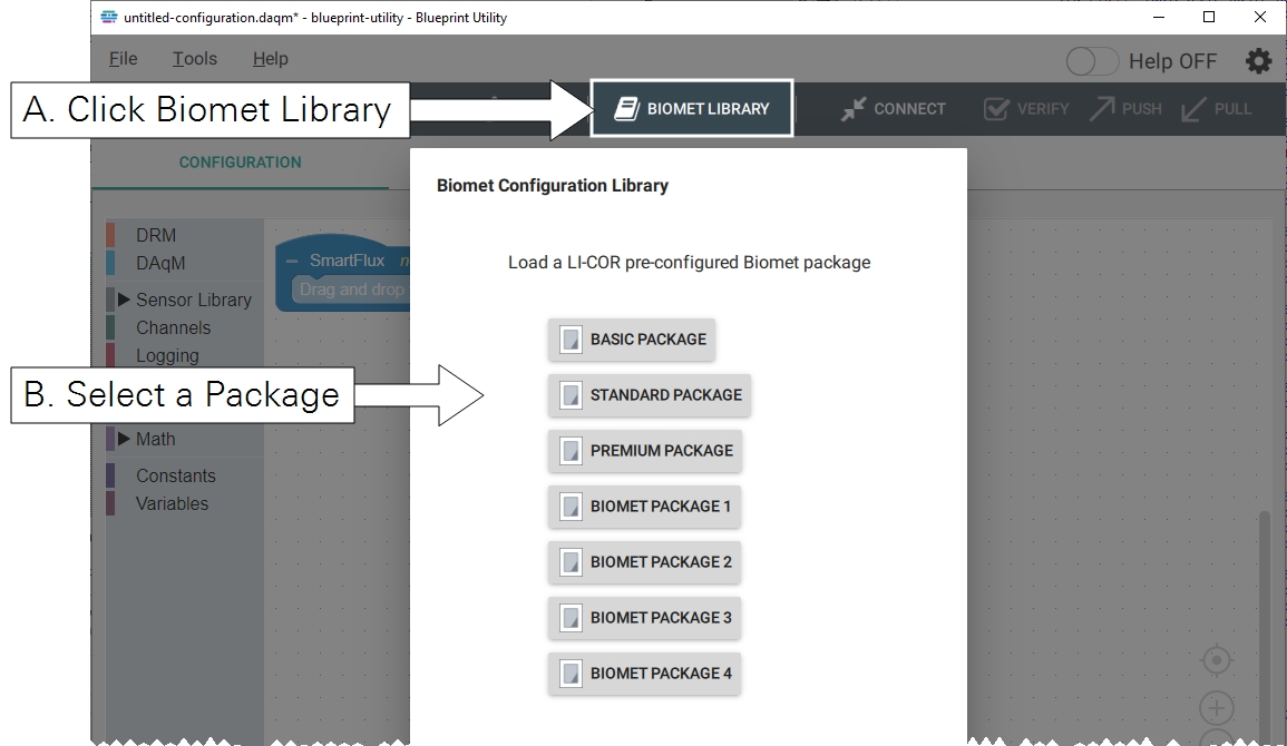
The first time it is opened, the Blueprint Utility presents a blank program. Click Biomet Library and select the basic sensor package.
Connecting to a DAqM and DRM
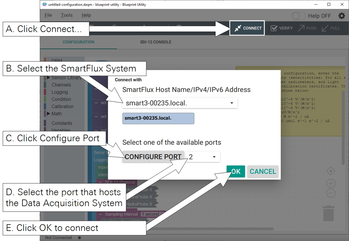
Click Connect. Identify your SmartFlux System from the list (you'll see the serial number followed by .local, like this: smartx-nnnnn.local, where nnnnn is the serial number). You can also enter the IPv4 or IPv6 address (Windows only) of the SmartFlux System. Click Configure Port and select the SmartFlux port number that the DRM or DAqM is connected to. Click OK.
Configuring Stevens HydraProbes
When connecting for the first time, each HydraProbe must be identified one at a time in the software. If you have already installed the HydraProbe leads, disconnect the power for two of them so that only one is powered on (the one you will designate as Sensor 1).
| From | Wire Color | To |
|---|---|---|
| SDI-12 Signal | blue | DIN Terminal 8 |
| SDI-12 Ground | black | DIN Terminal 9 |
| SDI-12 12 VDC | red | DIN Terminal 10 |
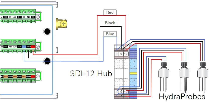
After connecting the first HydraProbe, click SDI-12 Console. Click Query All to make sure that the DAqM sees the sensor and that its address is 0.
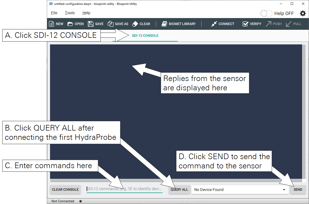
Enter the command 0A1 and click Send This command sets sensor 0 address (A) to 1; the default address is 0). The DAqM will respond with 1. Repeat this for the other HydraProbes, connecting the power wire for one sensor at a time and assigning each a unique address (0A2 for sensor 2, and 0A3 for sensor 3).
After each sensor has a unique address, you can set the soil type. For sensor 1, enter 1XW_SOIL_<G/O/R>! (where 1 is the sensor address and <G/O/R> represents the soil type (G for general, O for organic, and R for rockwool). Click Send to send the command. Repeat this for all SDI-12 sensors.
See Overview of SDI-12 commands for more information and details on using HydraProbes with older firmware.
Entering sensor calibration information (Basic Package)
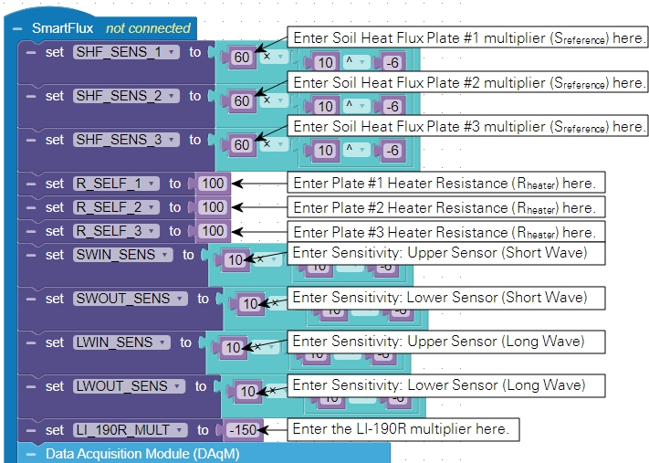
Each program includes some sensors that have specific calibration information. In Blueprint Utility, click the Configuration tab. The required information is described in a note in the program. In this collection of sensors, the soil heat flux plates, NR Lite 2 net radiometer, LI-200R, and LI-190R require calibration information.
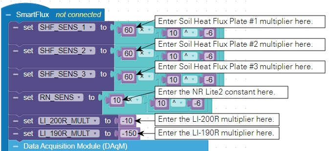
After entering the required information, save the configuration file to your computer.
Entering sensor calibration information (Standard Package)
Each program includes some sensors that have specific calibration information. In Blueprint Utility, click the Configuration tab. The required information is described in a note in the program. In this collection of sensors, the soil heat flux plates, NR01 net radiometer, and LI-190R require calibration information.
After entering the required information, save the configuration file to your computer.
Entering sensor calibration information (Premium Package)
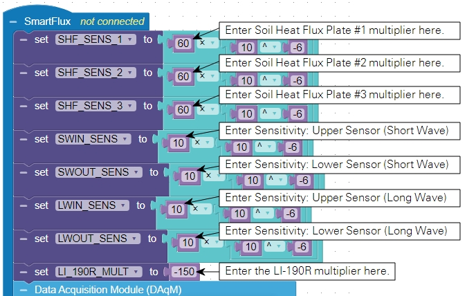
Each program includes some sensors that have specific calibration information. In Blueprint Utility, click the Configuration tab. The required information is described in a note in the program. In this collection of sensors, the soil heat flux plates, CNR4 net radiometer, and LI-190R require calibration information.
After entering the required information, save the configuration file to your computer.
Sending the program
Click Push to send the program. The parameters will take effect immediately.
Additional settings must be applied in order to log biomet data in eddy covariance datasets. These are described in the following section.
Connecting the biomet system to the EC system
When the system is properly configured, biomet data will be logged in each .ghg data file, which is processed by EddyPro on the SmartFlux System. The data acquisition system is compatible with the LI-7500DS (and SmartFlux 3 System) and the LI-7500A/RS or LI-7200/RS (and SmartFlux 2 System).
- Connect data cables for the system and power on the components.
- The DAqM, DRM, SmartFlux System, network switch, and gas analyzer all must be powered on.
- Launch the gas analyzer software and connect to the gas analyzer.
- The software is called something like LI-7x00 A RS DS x.x.x.
- Establish communication between the gas analyzer with the data acquisition system.
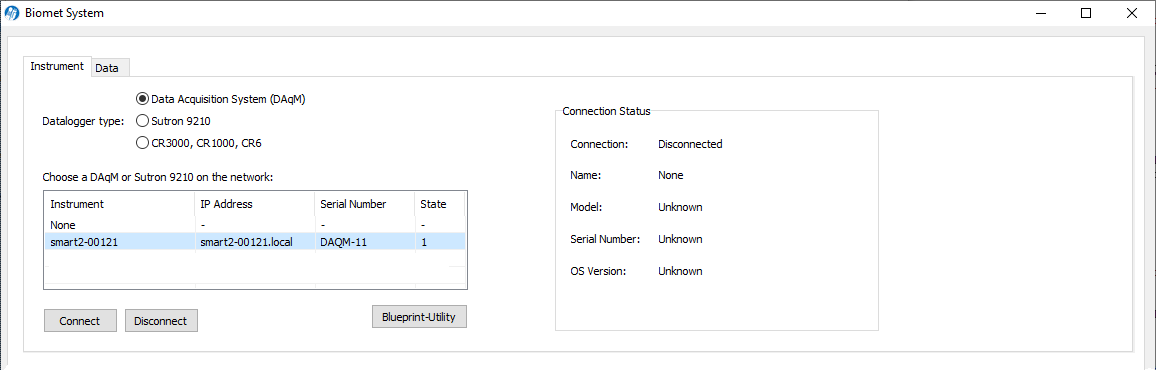
- Click the Biomet button. Under Datalogger type, select Data Acquisition System (DAqM). Select the SmartFlux System, click Connect, then click OK.
-

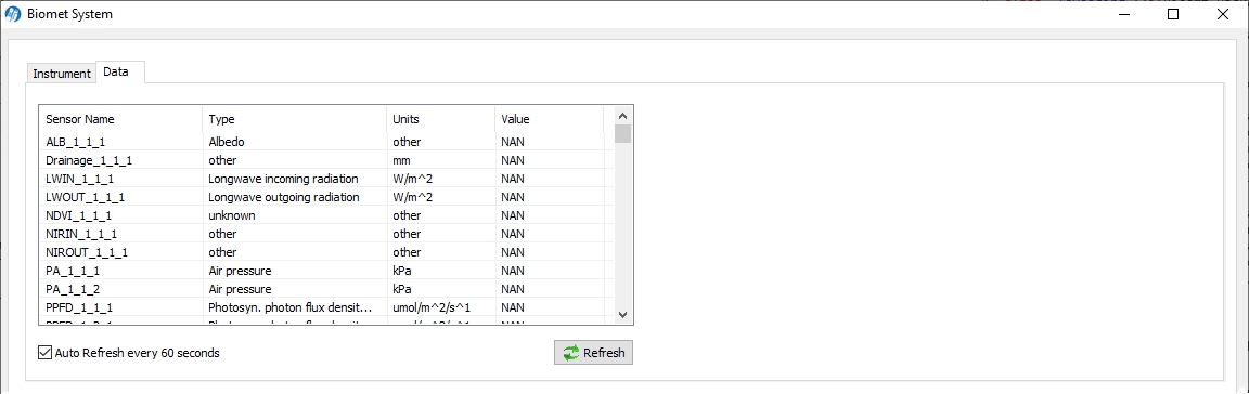
- View live data.
- Under the Data tab, you'll see live data values on the display. Readings are updated about once per minute.
Configuring the PhenoCam
Note: The StarDot NetCam SC (PhenoCam) has been replaced by a new model - the NetCamLIVE2. The NetCamLIVE2 is a direct replacement and is supported by SmartFlux 2 and 3 Systems (firmware v2.4.2 and newer).
The PhenoCam network1 provides extensive documentation for using this model of camera. Refer to their documentation (https://phenocam.nau.edu/webcam/) to configure the device according to those standards. Here, we provide basic instructions for configuring the device for LI-COR eddy covariance systems.
Setting the PhenoCam IP address
Download the StarDot Tools application from http://www.stardot.com/downloads and install it on your Windows computer.
- With the network and power cables connected as described earlier, power on system, including the camera.
- Launch the StarDot Tools application.
- The application will present all of the PhenoCams on your network. Identify the one you want to configure and record its ID and IP address.
- Enter the IP Address into a web browser address bar.
- The browser will display a recent image from the camera as well as some menu links.
- Click Config in the lower left of the page and log in when prompted.
-
- User Name: admin
- Password: admin
- Configure the image capture/upload timing.
- Click the Network tab and configure the settings:
-
- Under IP Assignment, select Manual.
- IP Address: 192.168.13.203 if following LI-COR recommendations (see Table 4‑4).
- Set the Subnet Mask: 255.255.255.0, typically.
- If you are using a cellular or satellite gateway to access your system remotely, under Network, set the IP Address to that of the cellular or satellite gateway. This will be provided by your service provider.
| Device | Public Start Port | Public End Port | Protocol | Host IP | Private Start Port |
|---|---|---|---|---|---|
| Phenocam | 7980 | 0 | TCP | 192.168.13.203 | 80 |
If your camera is on an unsecured network, it may be vulnerable to hacking. Therefore, we discourage using the camera in unsecured network environments.
Connecting the PhenoCam to the EC System
In the LI-7500A/RS/DS or LI-7200/RS software, connect with the gas analyzer that will be part of your eddy covariance system.
- Connect the camera network cable to the EC system network switch.
- Power on the system and the camera.
- Be sure that the camera is powered with 12 VDC.
- Click the SmartFlux button and select the PhenoCam tab.
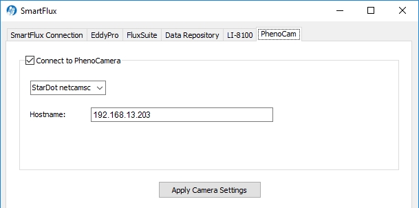
- Check Connect to PhenoCam.
- Select StarDot Camera from the menu.
- Enter the Hostname or IP Address (192.168.13.203) of the camera in the HostName field.
- Click Apply Camera Settings.
In this configuration, the system will store one image to the USB drive each day until about 7% of the capacity is occupied by images, at which time the old images will be deleted to make space for the new ones. If you use the FluxSuite server, your images will be posted once daily.
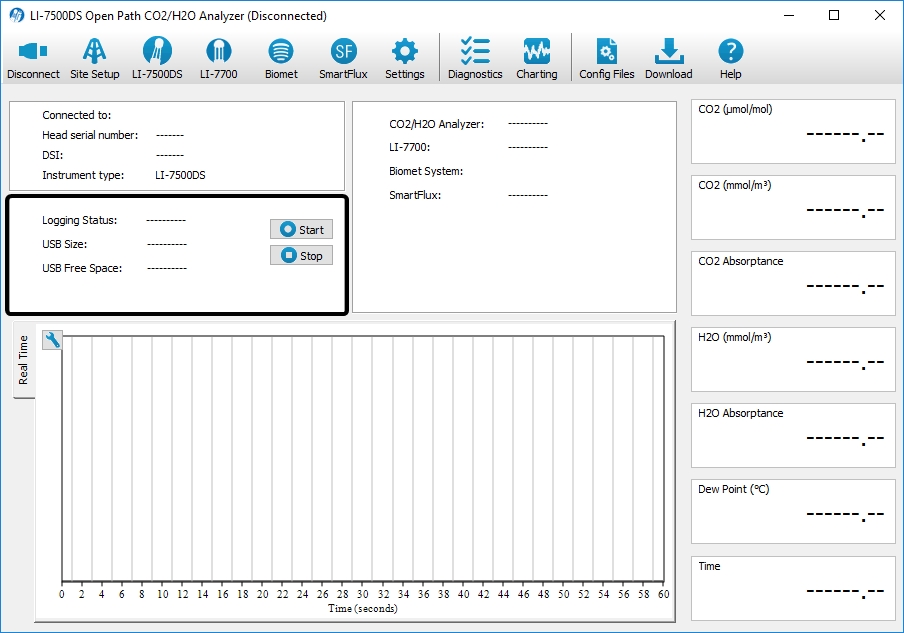
Turning ON datalogging
As part of an eddy covariance system, the DAqM and DRM provide data to the SmartFlux System for logging in eddy covariance data files. Logging is controlled in the LI-7500A/RS/DS or LI-7200/RS software. In the software dashboard, click Start or Stop to control logging. The logging setting will apply immediately.
All data files are stored on the USB drive on the SmartFlux System. Most files are saved on the USB drive in the LI-7550, except for the data acquisition system backup file. On the SmartFlux USB drive, the data are in the compressed .ghg files and a separate folder of biomet data backup files (called something like licor/data/daqm/YYYY-MM-DD-HHMMSS-daqm.zip). See Viewing and evaluating data for more details.