Blueprint Utility software reference
The Blueprint Utility provides a great deal of flexibility for custom programming. Here we begin with an overview of the basic features and terms, and then we describe how to create some custom programs. In this section, we provide an overview of the Blueprint Utility.
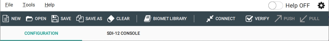
Menu items
The top menu bar provides some familiar options, including File, which presents ways to access and create files, Tools, which has options to update firmware or send a calibration file, and Help, which provides information on the application.
Some familiar items (New, Open, etc.) are given below the drop-down menus, followed by some not-yet familiar items.
- Biomet Library: Click to load a program from the library. These are for use with LI-COR biomet programs that correspond with biomet sensor packages.
-
- Verify: Check a program for conflicts and errors. If there are conflicting variable names or an invalid configuration, an error will be triggered, as well as guidance to resolve the issue.
- Push: Sends the configuration to the DAqMs and DRM.
- Pull: Loads the configuration from DAqMs and DRM.
- Help: The software provides built-in help. Click to hide or show the help.
- Settings: To configure the general settings for the application.
- Configuration: A tab where you load, create, and configure the program. This tab is described in the remainder of this section.
- SDI-12 Console: A tab where you configure SDI-12 sensors. See SDI-12 Console for more information.
Connect screen
Clicking Connect opens the connect screen, where you establish communication with the DRM and DAqMs connected to your SmartFlux System. (Communication with the DRM and DAqMs is mediated through the SmartFlux System.) Normally, the Blueprint Utility will display a list of all SmartFlux Systems on your network, and all you need to do is select one. The first time you connect, click Configure Port and select the SmartFlux port number that the DAqM/DRM is connected to.
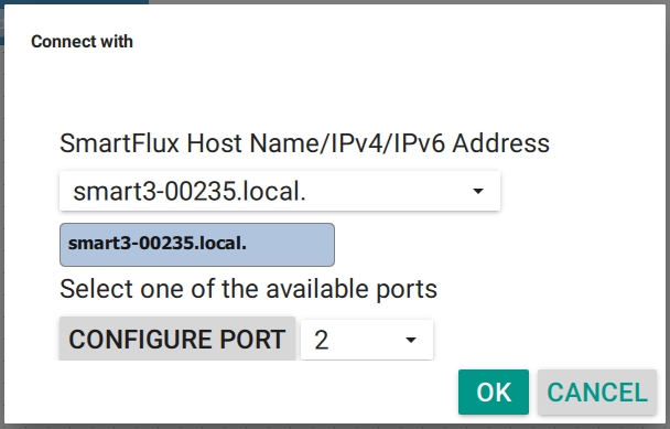
You can also connect by entering the Host Name (like smart3-nnnnn.local., where nnnnn is the serial number), the IPv4 address, or the IPv6 address (on Windows computers).
Blueprint Utility configuration files
The Blueprint Utility creates a configuration file that can be saved to your computer and loaded to the DAqMs and DRM. Files have a *.daqm extension. They are XML files that can be viewed in any text editor. Due to the complexity of the file structure, we recommend that you only edit a file in the Blueprint Utility.
Blueprint Utility workspace actions
The workspace is configured with some basic interactions:
- Drag and drop: Add an item (e.g., Data Acquisition Module, a sensor, a channel, etc.) by dragging and dropping it into the workspace.
- Snap into place: When an item is compatible with another item, it will "snap" into place. If it isn't compatible, you can leave the item in the workspace while you add other items.
- Delete: Drag an item into the trash, select the item and press the Delete or Backspace key, or right click and select Delete.
- Click to pan: Click and drag to move the view.
- Zoom in, zoom out, center the view: As your program grows, you'll find these options to be useful. Zoom with Ctrl + Scroll Mouse Wheel.
Right-click to customize a block. Some or all of the options will be presented:
- Duplicate: Like copy and paste, but in one action.
- Inline/External Inputs: Change the arrangement from vertical to horizontal.
- Collapse/Expand Block: Hide or show the items within a block. The same as clicking the plus (+) and minus (-) buttons.
- Add/Remove Comment: Right-click and select Add Comment. Add your notes to the comments bubble. Comments are for your records.
- Delete Block: Removes a block from the workspace.
Keyboard shortcuts
Application shortcuts are general for the software. These interactions are related to file management and interactions with the DAqM and DRM.
| Application Shortcuts | Keyboard Shortcut |
|---|---|
| New configuration file | Ctrl + N |
| Open a configuration file | Ctrl + O |
| Save | Ctrl + S |
| Save As | Ctrl +Shift + S |
| Clear | Ctrl + R |
| Biomet Library | Ctrl + B |
| Connect with a DAqM or DRM | Ctrl + T |
| Verify configuration | Ctrl + F |
| Push configuration | Ctrl + U |
| Pull configuration | Ctrl + L |
Workspace shortcuts are used to work with a program in the workspace.
| Workspace Shortcuts | Keyboard Shortcut |
|---|---|
| Copy block | Ctrl + C |
| Paste block | Ctrl + V |
| Duplicate selected block | Ctrl + D |
| Collapse or Expand selected block | Ctrl + E |
| Delete selected block | Backspace |
| Undo last action | Ctrl + Z |
| Redo last action | Ctrl + Y |
| Help (on the selected item) | F1 |
| Quit the application | Ctrl + Q |
| Zoom in or out | Ctrl + Mouse Wheel |
Verification tests
The Blueprint Utility can test a program for over fifteen potential issues. Familiarize yourself with these tests and results so that you can construct operational programs from the outset. The tests should be used to check a program after you are done creating it. When an issue is detected, you'll also be presented with information that will help you solve the problem. Here we describe the tests in more detail.
- Disabled or not connected block: All disabled or not connected blocks have to be removed from the workspace, connected to a suitable block, or otherwise enabled following the warning suggestions. To see hidden blocks you can use the context menu Clean up Blocks action (right-click on the workspace). Delete, connect, or enable blocks to resolve the issue.
- Duplicate constant: A duplicate Set Constant block is defined for the same constant. Delete the unused one to resolve the issue.
- Constant not set to any value: A Set Constant block is defined but not set to any value. Enter a value to resolve the issue.
- Too many computed channels: A limited number of computed channels is allowed, including calibration channels.
- DRM not connected above DAqM: A DRM block, although optional, must be connected above all the existing DAqM blocks. If your program includes a DRM, it must precede any DAqM blocks.
- Duplicate DAqM variable: A DAqM variable (input voltage or internal temperature) is already in use in a different DAqM configuration.
- Duplicate channel variable: A variable already associated to a channel cannot be used for a different channel because this would result in two variables logged with the same name. For one of the duplicates, choose a different, unused variable, or create a new variable with a unique name.
- Duplicate hardware channel: A hardware channel cannot be used multiple times inside the same DAqM configuration. This is telling the software that two sensors are connected to the same terminals, which is not possible. The software will identify one of the channels to help you find and resolve the issue.
- Unassociated constants: A constant used in an equation or calibration block is not associated with any channel.
- Unassociated variable: A variable used in an equation or calibration block is not associated with any channel.
- Inconsistent noise rejection settings: All DAqM blocks have to be setup with the same Noise Rejection value. Change the noise rejection settings so that they are all the same (either 50 or 60 Hz).
- Equation variable recursion: A variable associated with a computed channel cannot be used in its own equation block. The software will list the variable name to help you find and resolve the issue.
- Inconsistent logging interval settings: All DAqM blocks have to be set up with the same Logging Interval. Check the settings for each DAqM block and change one or more to make them compatible.
- Inconsistent sampling interval settings: All DAqM Sampling Intervals need to be submultiples of the Logging Interval. For example, a Logging Interval of 20 seconds is not compatible with a Sampling Interval of 15 seconds. You can resolve the issue by changing either the Sampling Interval or the Logging Interval.
- Duplicate SDI-12 address: SDI-12 sensor addresses have to be unique in each DAqM configuration. While connected to your system, go to the SDI-12 tab and click Query All. The interface will return the addresses of all SDI-12 sensors that are connected. Physically disconnect the wire leads one sensor at a time, followed by Query All. When you have identified the improperly addressed sensors, reconnect them one at a time, and set the addresses one at a time until each sensor has a unique address. See Support: Biomet Data Acquisition System and Blueprint Utility for details.
- Too long equation: A computed channel equation exceeds the maximum allowed length.
Configuration items
On the left, the Blueprint Utility provides blocks that can be dragged and dropped into the workspace. When you create a new program, the workspace will include the mandatory SmartFlux block. All communication is mediated through a SmartFlux System.
SmartFlux block
The "fundamental unit" of programming in the Blueprint Utility, the SmartFlux Block is required for any program. When connected to a SmartFlux 2 or 3 System, the HostName will be presented in the top of this block (but you do not need to be connected in order to write the program). The SmartFlux block accepts one DRM block and up to four DAqM blocks. The DRM block must be above DAqM blocks.
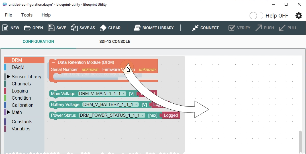
DRM (Data Retention Module) block
Fits into a SmartFlux block; specifies the presence of a Data Retention Module. The DRM block must be above any DAqM blocks. When you connect to a DRM, the Serial Number and Firmware Version will be read from the DRM. The DRM can measure and log the main power voltage, battery power voltage, and the power supply status.
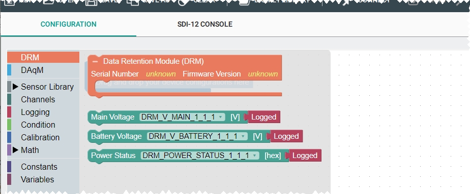
Main Voltage
Fits into the DRM block. Accepts a Logged block. Instructs the system to log voltage (V) supplied to the power in terminals. Pre-populated with a main voltage variable and a Logged block.
Battery Voltage
Fits into the DRM block. Accepts a Logged block. Instructs the system to log voltage (V) supplied to the +12V BAT terminals. Pre-populated with a battery voltage variable and a Logged block.
Power Status
Fits into the DRM block. Accepts a Logged block. Instructs the system to log an integer in the range of 0 to 65535, which indicates the status of power supplied to the DRM and power delivered over the outputs (see Table 9‑1). It is pre-populated with a power status variable and a Logged block. The diagnostic can be used to identify faults in the voltage outputs or determine how the DRM was powered during a time period. Online utilities are available to convert the integer to binary (search for integer to binary in a search engine).
Example: If the integer of 15 is logged, it decodes to binary of 0000000000001111, is the bits in the order of position 15 to 0. This indicates that the V1, V2, V3, and V4 are powered on. No other statuses are triggered.
Example: If the integer of 36623 is logged, it decodes to binary of 1000111100001111, which is bits in the order of position 15 to 0. This indicates that the device was running from backup battery power; V1, V2, V3, and V4 each had a fault; and V1, V2, V3, and V4 were powered on.
DAqM (Data Acquisition Module) block
Fits into a SmartFlux block; specifies the presence of a DAqM, sets the logging interval for connected sensors, and sets the main power noise rejection. When you connect to a DAqM, the Serial Number and Firmware Version will be populated by the device. By default, includes an SDI-12 Protocol block and a Sampling Interval container blocks. The DAqM block can be configured to record the DAqM's input voltage, internal temperature, and data from connected sensors. DAqM blocks must be in the order that DAqMs are wired together (the DAqM closest to the DRM or SmartFlux System corresponds with the first DAqM block in your program).
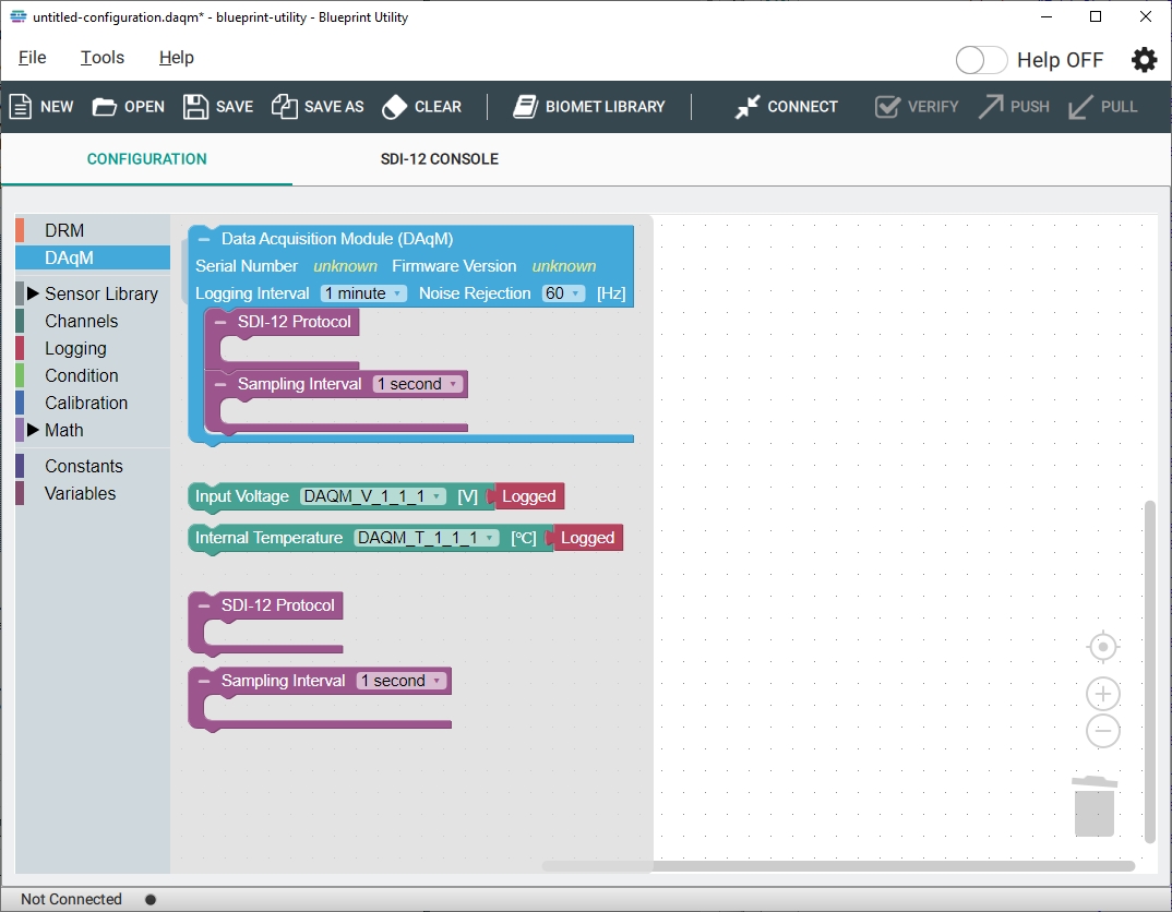
DAqM Input Voltage
Fits into a DAqM block. Accepts a Logged block. If logged, the voltage supplied to the DAqM will be recorded in the data set.
Internal Temperature
Fits into a DAqM block. Accepts a Logged block. If logged, the temperature of the DAqM will be recorded in the data set.
SDI-12 Protocol
Fits into a DAqM block. Accepts a Stevens HydraProbe block or a generic SDI-12 Sensor block. Required if you use SDI-12 sensors.
Sampling Interval
Fits into a DAqM block. Accepts any block from the sensor library except SDI-12. It provides the top level control over sensors and specifies the sampling interval for sensors within. You can enter a value and units (for example, 1 second) to specify how often sensors are sampled. Each sample is used to compute the average that is recorded at the logging interval.
Sensor Library
The Sensor Library includes pre-configured blocks for all supported sensors and generic blocks that are for other sensors. Expand it to see a list of sensors that have pre-written configurations and the generic sensor, which can be customized.
Generic sensors
Select a generic sensor from the list if your sensor is not included in the default sensor list. If you are adding any of the sensors from the list, you can start with the blocks for that sensor. The Generic Sensors block can be used to add other sensors.
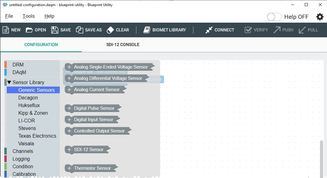
Analog single-ended voltage sensor
Fits into Sampling Interval block. Accepts any one of the Channel blocks. You can name the variable here. Includes one analog single ended voltage channel block, which reads voltage at the assigned channel. Includes a computed channel block, which transforms the voltage into more meaningful values. The computed value and statistics are logged (if the logged block and statistic blocks are present).
Analog differential voltage sensor
Fits into Sampling Interval block. Accepts any one of the Channel blocks. You can name the variable here. Includes one differential voltage channel block, which reads the voltage differential at two assigned channels. Includes a computed channel block, which transforms the voltage into more meaningful values. The computed value and statistics are logged (if the logged block and statistics block are present).
Analog current sensor
Fits into Sampling Interval block. Accepts any one of the Channel blocks. You can name the variable here. Includes one analog current channel block, which reads the current at the assigned channel. Includes a computed channel block, which transforms the voltage into more meaningful values. The computed value and statistics are logged (if the logged block and statistics block are present).
Digital pulse counting sensors
Fits into Sampling Interval block. Accepts any one of the Channel blocks. Includes a Digital Pulse block and a Computed Channel block. You can name the variable here.
Digital input sensors
Fits into Sampling Interval block. Accepts any one of the Channel blocks. Includes a Digital Input block and a Computed Channel block. You can name the variable here.
Controlled output sensors
Fits into Sampling Interval block. Accepts a Controlled Output channel block and a Computed Channel block. You can name the variable here.
SDI-12 sensors
Fits into SDI-12 Protocol block. Accepts an SDI-12 measurement block. You can name the variable, set the address, and specify the measurement set to expect from the SDI-12 sensor.
Thermistor sensor
Fits into Sampling Interval block. Accepts a Thermistor and a Computed Channel block with the Steinhart-Hart Thermistor block. You can name the variable here.
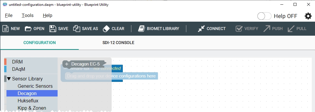
Decagon
To connect a Decagon Devices EC-5. Fits into Sampling Interval block. Accepts an Excitation block, Analog Single-Ended Voltage block, and a Computed Channel block.
Hukseflux
To connect HFP01, HFP01SC and NR01.
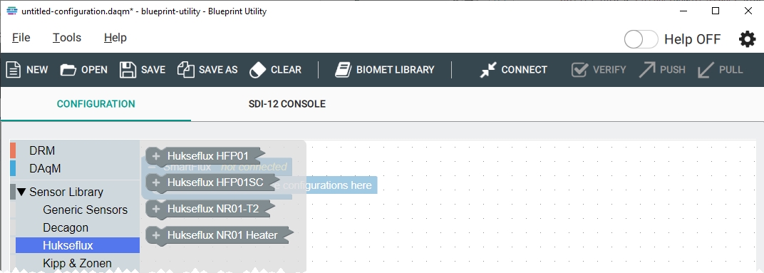
HFP01 and HFP01SC
Fits into Sampling Interval block. Accepts an Analog Differential Voltage block and a Computed Channel block. For the self-calibrating soil heat flux plates, you can also add a Calibration block.
NR01-T2
To connect the NR01-T2. Fits into Sampling Interval block. Accepts Analog Differential Voltage blocks and Computed Channel blocks for the Thermistor block.
NR01 Heater
To configure the heater on the NR01-T2.
Kipp & Zonen
To connect a net radiometer and accessories.
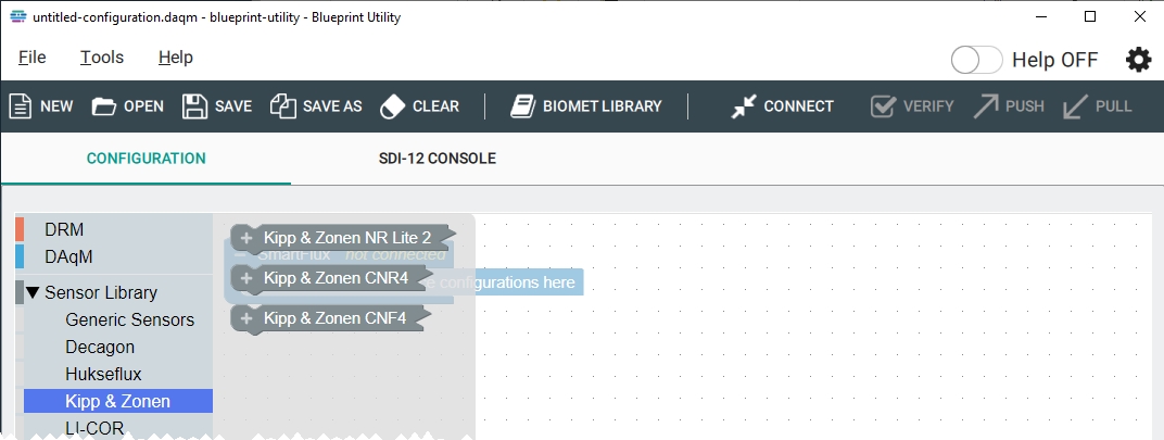
NR Lite2
To connect an NR Lite2. Fits into Sampling Interval block. Accepts an Analog Differential Voltage block and a Computed Channel block.
CNR4
To connect an CNR4. Fits into Sampling Interval block. Accepts an Analog Differential Voltage block and a Computed Channel block. Since the sensor has more than four outputs, you'll configure at least four Analog Differential Voltage inputs and at least four corresponding Computed Channels. In the biomet programs, additional parameters are computed, including temperature (K), albedo, and net radiation.
CNF4
To connect the CNF4 heater and ventilation unit to the CNR4 Net Radiometer. Fits into the Sampling Interval block. Accepts Controlled Output blocks, which can be configured to activate switched power outputs.
LI-COR
To connect LI-190R, LI-200R, or 7900-180 Soil Temperature Probe.
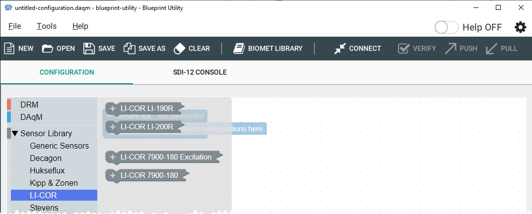
LI-190R
To connect the LI-190R Quantum Sensor. Fits into the Sampling Interval block. Accepts an Analog Current block and a Computed Channel block.
LI-200R
To connect the LI-200R pyranometer. Fits into the Sampling Interval block. Accepts an Analog Current block and a Computed Channel block.
LI-COR 7900-180 Excitation
To configure the excitation voltage to the 7900-180 soil temperature thermistor. Compatible with Analog channels 15 and 16 with excitation voltage. Fits into the Sampling Interval block. Accepts an Excitation Channel block.
LI-COR 7900-180
To connect the 7900-180 soil temperature thermistor. Compatible with Analog channels 15 and 16 with excitation voltage. Fits into the Sampling Interval block. Accepts an Analog Single-Ended Voltage block and computed channel blocks.
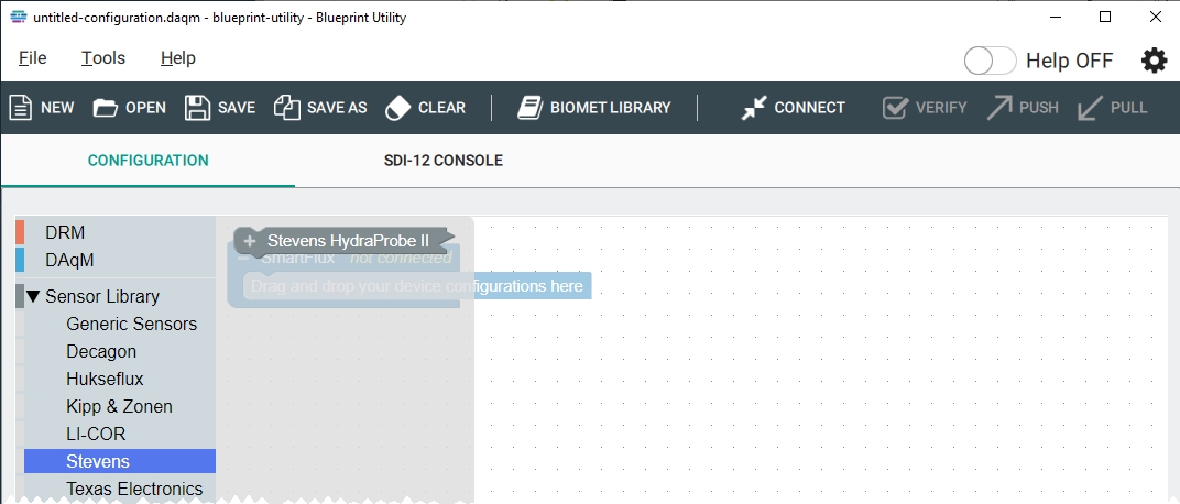
Stevens
To connect Stevens HydraProbes. Fits into SDI-12 Protocol block. Accepts SDI-12 Measurement blocks. One SDI-12 measurement block is needed for each variable logged. Biomet programs log Soil Water Content and Soil Temperature, and thus include two SDI-12 measurement blocks by default.
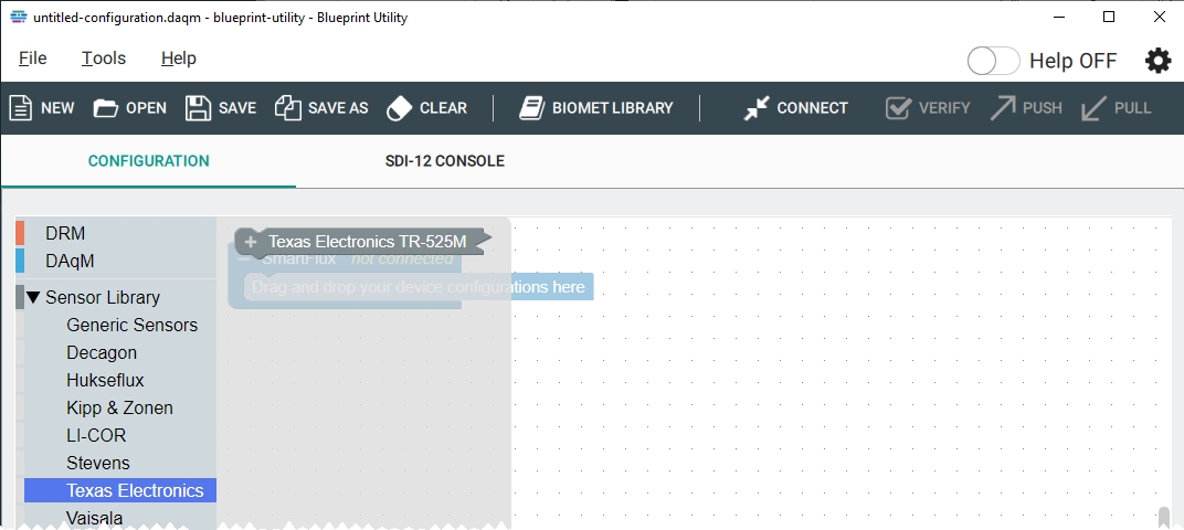
Texas Electronics
To connect a TR-525M tipping bucket rain gauge. Fits into Sampling Interval block. Accepts a Digital Pulse block and a Computed Channel block.
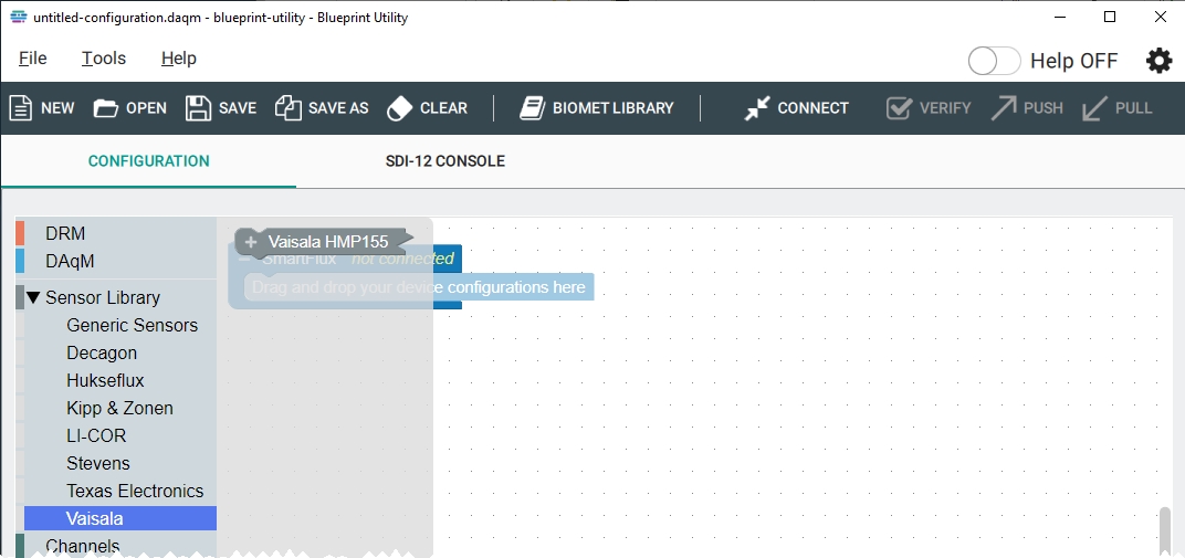
Vaisala
To connect an HMP155 HUMICAP® Air Humidity and Temperature Sensor. Fits into Sampling Interval block. Accepts one Analog Single Ended Voltage block and one Computed Channel block for each variable to be logged.
Channels
A channel specifies which terminals are in use. Each channel will be associated with a variable. When you add a channel to the workspace, it may automatically create a variable (unless a suitable variable already exists).
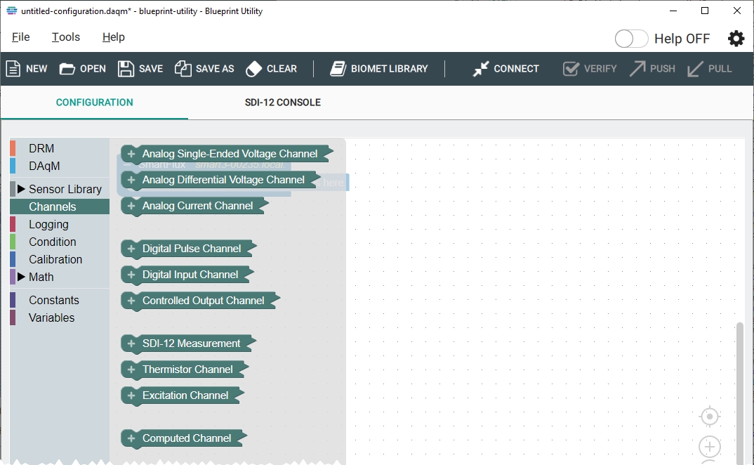
Analog Single-Ended Voltage Channel
For analog single-ended sensors such as a Vaisala HMP155. Select a variable name, Channel, and Range (volts or mV). Fits into any block from the Sensor Library except SDI-12.
Analog Differential Voltage Channel
For analog differential sensors such as HFP01 Soil Heat Flux Plates. Select a variable name, Channel pair, Range (volts or mV), and whether a pull-down resistor is used. Fits into any block from the Sensor Library except SDI-12.
Analog Current Channel
For analog single-ended sensors with a current signal such as the LI-200R. Select a variable name, Channel, and Range (micro amps). Fits into any block from the Sensor Library except SDI-12.
Digital Pulse Channel
For pulse counting sensors such as a tipping bucket rain gauge. Select a variable name and channel. Fits into any block from the Sensor Library except SDI-12.
Digital Input Channel
Used to read a digital signal over the specified channel C1, C2, C3, or C4. Fits into a Digital Input Sensor Block or a Controlled Output Sensor block.
Controlled Output Channel
Controls power to SW1, SW2, or SW3 and digital channels C1, C2, C3, and C4. Outputs a digital signal over the specified channel. Includes a check-box that, when checked, instructs the system to turn off power or open the switch when the system is powered by the backup battery.
SDI-12 Measurement
For SDI-12 sensors such as the Stevens HydraProbe. Select a variable name, Measurement # (1 to 9), and units. Fits into SDI-12 Sensor block.
Thermistor Channel
For temperature sensors. Select a variable name and channel. Fits into any block from the Sensor Library except SDI-12.
Excitation Channel
For analog sensors that require excitation voltage (channels A15 and A16 only). Select a variable name and channel. Fits into any block from the Sensor Library except SDI-12.
Computed Channel
To perform a mathematical transformation of an input variable. Select a variable name and units. Then add a Logged node to log the computed value, add a Statistics node to record statistics, and add an equation node to transform the value prior to logging. Fits into any block from the Sensor Library except SDI-12.
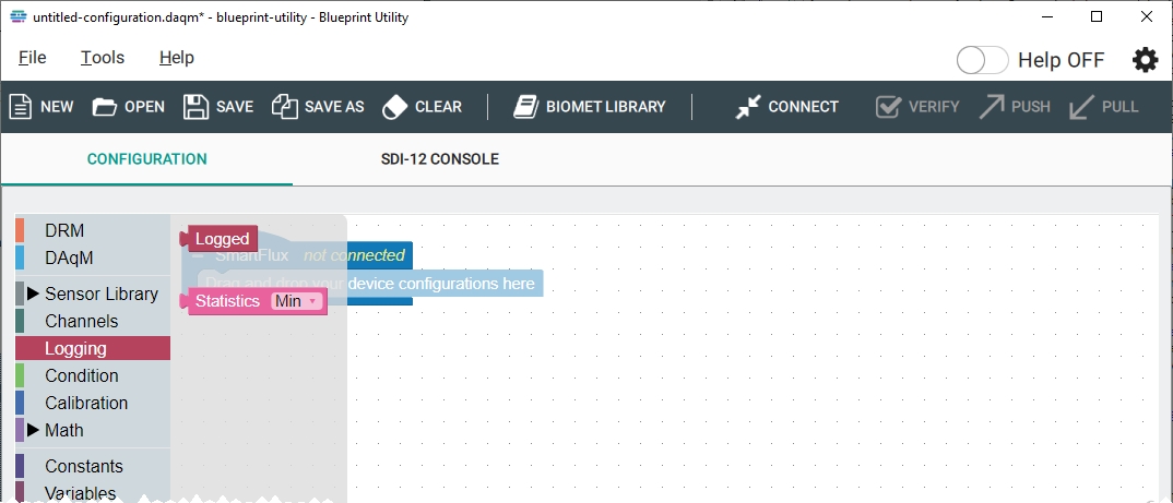
Logging
Instructs the system to log data and statistics. Both fit into any Channel block.
Logged
When added to a channel, the Logged block instructs the system to log the variable.
Statistics
Instructs the system to log statistics, which can be minimum, maximum, total, or average.
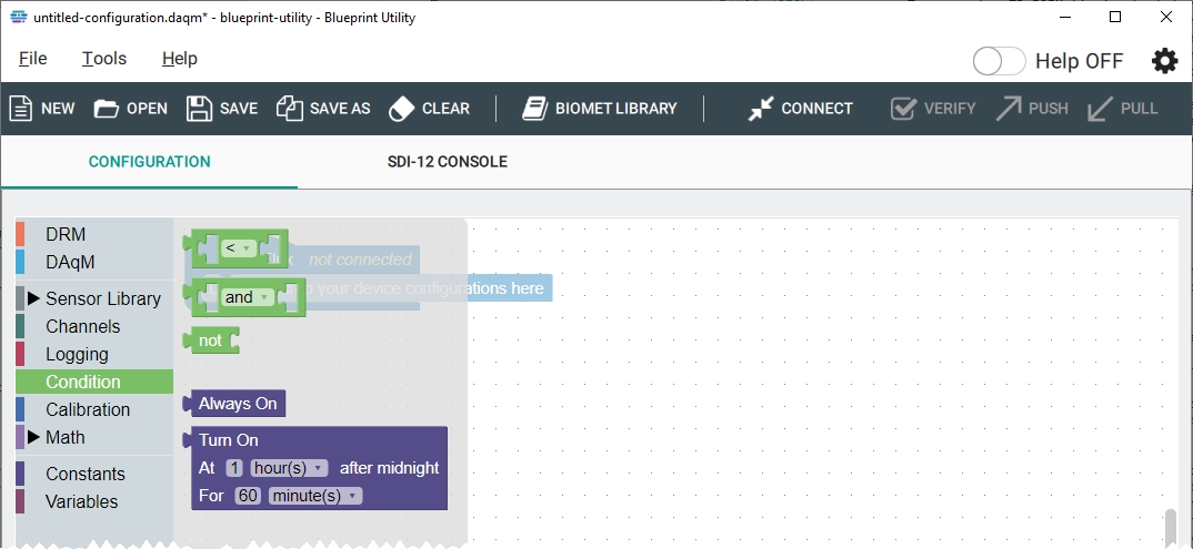
Condition
Conditions are logical operators and controls for switched power supplies, for example.
Logic
One block provides greater than (<) and less than (>) operators. Another block provides the operators and as well as or. A third block provide a not operation.
Controls
Controls are used to configure a power output, like with the CNF4 heater and ventilator unit. Always On means the switched output will be on when the DAqM is powered on. Turn On lets you set time in relation to midnight and duration that the power is to be applied.
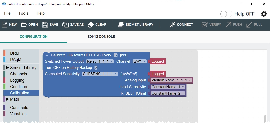
Calibration
The Calibration block is specific to control self-calibrating soil heat flux plates. Controls timing of recalibration, which variable controls the switched power supply, which channel sends the signal, and what to name the new computed sensitivity value. Also requires an you to specify an Analog Input channel, a variable for Initial Sensitivity, and a variable for R_SELF. Only fits into Hukseflux HFP01SC block. Includes a check-box that, when checked, instructs the system to disable the calibration function when the system is powered by the backup battery.
Math
Operations can be configured and performed on any input. Basic math and Equations fit into any Computed channel block and others. Four items are included under basic math.
Basic
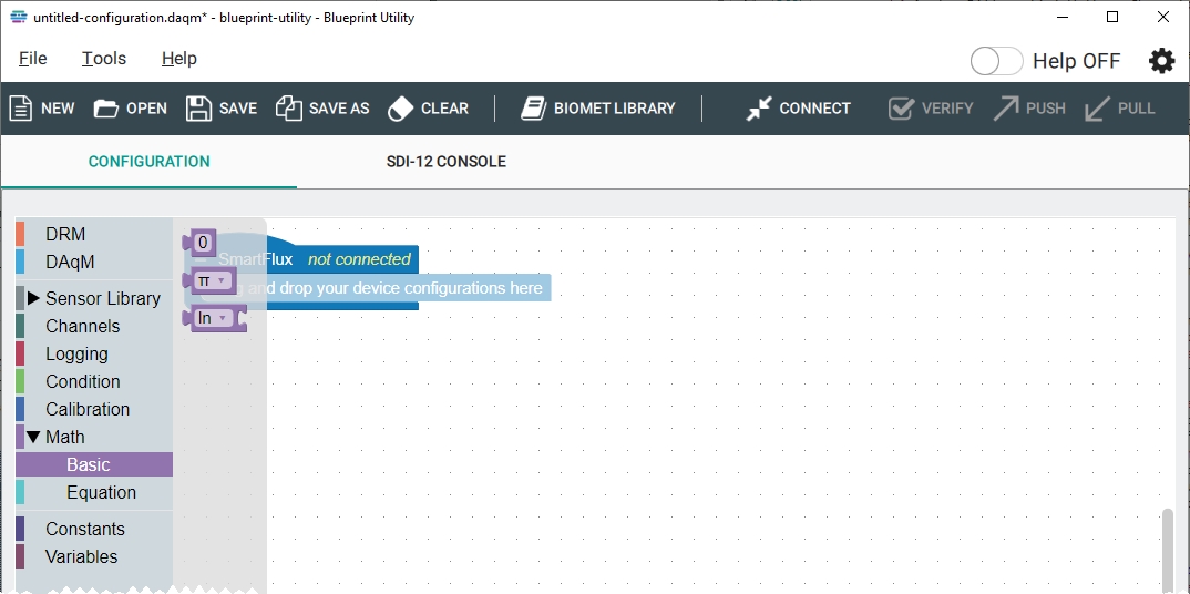
- A value node displays a 0 by default. You can enter any value in place of the 0.
- A transformation node displays the π symbol by default. You can choose pi (π), exponent (e), phi (φ), square root of two (sqrt(2)), or inverse square root (sqrt(½)).
- An operator node can be used to take the natural log (ln), log base 10 (log10), absolute value , or flip the sign of a variable (-).
Equation
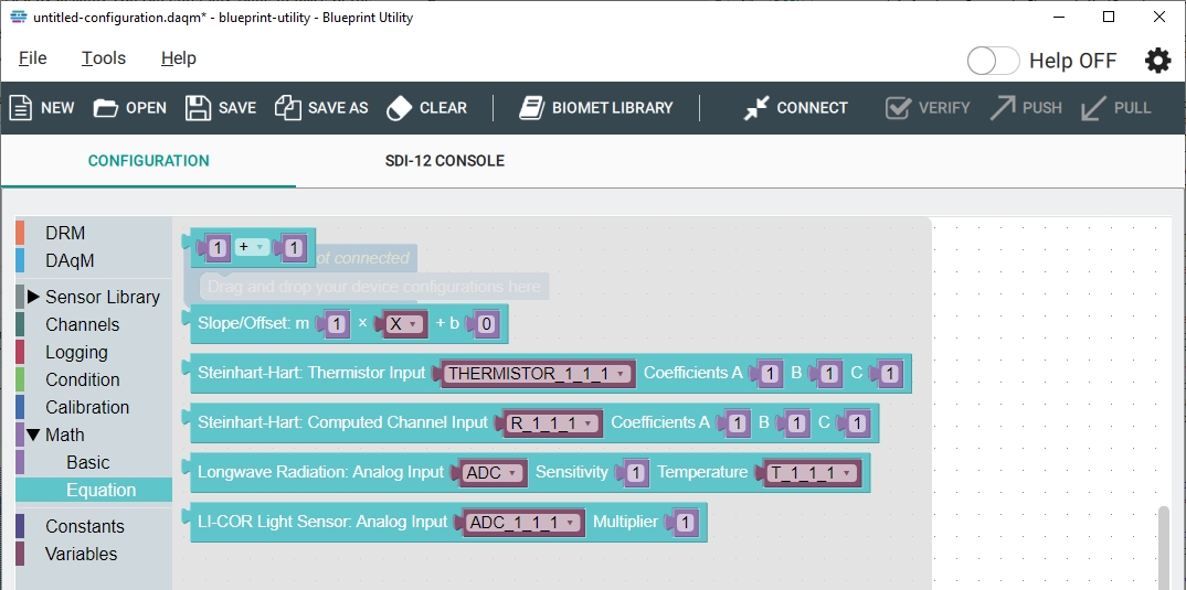
- A basic equation node has a value (which can be a variable, constant, or entered value), mathematical operator (+, -, ×, ÷, or ^), and a second value (which can be a variable, constant, or entered value). Equation nodes can be nested, giving you the opportunity to construct some complex computations.
- Slope/Offset: y = m × x + b. You can specify m, x, and b.
- Steinhart-Hart: Thermistor input. Applies the transformation to the inputs on channels A15 and A16.
- Steinhart-Hart: Computed channel input. Applies the transformation to a variable.
- Longwave Radiation: To apply calibration the factor (sensitivity) to an analog input.
- LI-COR Light Sensor: To apply the calibration multiplier to an LI-190R or LI-200R.
Constants
Constants are values that do not change, such as a calibration multiplier. Constants are empty when you load a new configuration. If you load a program from the Biomet Library or add an element to a program that includes a constant, constants are added that support your program. Constants fit into any Computed channel block and several others.
The Set Constant To block is used to add a multiplier for calibration constants, for example.
- Create constants: Click to create a constant. You will be prompted to name the constant. The software will automatically create a constant block that allows you to set the value of the constant to numeric value or a variable.
- Delete all constants: Removes all constants from the current configuration even if they are used in the program. You'll be prompted to delete each constant and block that uses it.
- Delete all unused constants: For housekeeping in your program. Click this to remove constants that are not used.
Variables
Variables represent a logged parameter or a parameter that is read (e.g., to read the voltage on a particular channel). Variable names require specific numeric identifiers that denote the spatial position and replicate (*_n_n_n), which is described in The relationship between variable label and sensor position. This standard is enforced in the workspace by requiring each variable to include the underscores and numbers before it can be created. A variable for soil heat flux can be named SHF_1_1_1, configured to log the data from a soil heat flux plate. Variables are empty when you load a new configuration. If you load a program from the Biomet Library or add an element to a program that includes a variable, variables are added that support your program. Variables fit into any Computed channel block and others.
SDI-12 Console
The SDI-12 console is used to configure SDI-12 sensors. This may include setting a sensor's address or specifying the variables it sends. You must be connected to the DAqM through the computer software to send the command, and the power and data wires from the sensor must be connected to DAqM to receive the command.
Important: Although not desirable, the software does allow you to unwittingly set one sensor's address to the address of another simply by running the command to change an address. In this case, you'll have to manually disconnect the power to one of the sensors and reset the other sensor's address.
If you have multiple DAqMs, you have to specify which one your are talking to when configuring SDI-12 sensors. Setting an address: HydraProbes have a default address of 0; other SDI-12 sensors may have a different default address. SDI-12 sensors should be connected one at a time and given a unique address until each one has a unique address. To change the address from 0 to 1, connect the first sensor, and click Query All to request the address of the sensory. Enter the command of 0A1 and click Send (the command indicates set sensor 0 address (A) to 1). The datalogger will find the sensor, and set the address to 1. To change the second sensor address, connect it, then enter the command 0A2, and click Send. Additional commands are described in Support: Biomet Data Acquisition System and Blueprint Utility.
Tools menu
The Tools menu provides options to update the DAqM or DRM firmware and to upload calibration data for the DAqM or DRM.
Update firmware
The Blueprint Utility includes copies of compatible embedded firmware for both the DAqM and the DRM. If updated firmware is released, you will get it when you install an update to the Blueprint Utility. To load a new version of the embedded firmware to your DAqM or DRM:
- Be sure you have the latest version of the Blueprint Utility.
- Go to licor.com/support/Biomet-System/software.html and check the software version. In the Blueprint Utility, click Help > About to see the software version. If an update is available, download it and install it on your computer.
- Connect with the SmartFlux unit that is hosting your DRM and DAqM.
- In the Blueprint Utility, click Tools > Update Firmware.
- The software will indicate if an update is available for the DAqM or the DRM.
- Under Available devices, select the DAqM or DRM that you want to update and click Update. We recommend starting wih the last DAqM in the chain.
- The new software will be installed on the DAqM or DRM. Update all of the components that are part of your system.
Device calibration
Each DAqM has a unique internal calibration file. Although you should not need to update the calibration or recalibrate the DAqM under normal circumstances, you have the option to view calibrations and upload a calibration file if something unexpected happens. Contact LI-COR technical support if you suspect that there are issues with the calibration and to obtain a copy of your calibration data.
To view the current calibration:
- Connect to the system.
- Click Tools > Device Calibration.
- Select the DAqM of interest.
- Click Receive Calibration.
- Review the calibration values. Typically, they are very close to 1 for each channel.
To load a calibration file on a DAqM, see Loading a DAqM calibration file.
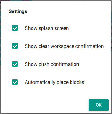
General settings
The gear icon in the top right of the display provides access to general settings for the application. Click the gear ( ) to open the options: