Initial setup
This section describes how to assemble, deploy, and maintain the communication system. The following tools are required:
- Phillips screwdriver
- Bolt drivers, wrenches, or adjustable wrench (16 mm, 13 mm, and 8 mm)
- Standard slotted screwdriver (optional, instead of 8 mm bolt driver)
- Post driver for antenna post
The hardware installation will take about 30 to 60 minutes. Software configuration will take about 15 to 30 minutes. Activating the terminal depends upon the wireless service provider.
General steps
Note: We highly recommend that you fully assemble the system, configure your network account, and test the system in your office or lab before deploying it in the field.
1. Arrange a data plan
Important: Be sure that your service provider supports two-way communication and that they have configured your account to allow two-way communication through their firewall.
2. Assemble the system
Assemble the components and install the data cables and power supply cables for the system. See Initial assembly.
3. Configure the satellite gateway
Some settings in the gateway must be configured in order to connect to the network. These are described in Configuring the communication system.
4. Configure the sensor network
The terminal and instruments must be configured to communicate with each other.
- For a basic CO2/H2O eddy covariance system see Configure LI-7500x or LI-7200x eddy covariance system communication.
- To add an LI-7700 see Configure LI-7700 communication.
- To add a Biomet System (Sutron) see Configure Sutron biomet system communication.
- To add an LI-8100A Soil Gas Flux System see Connecting with an LI-8100A.
5. Connect to the system
If everything is configured properly, you'll be able to access your eddy covariance system from any computer on the internet and download data, connect with web services such as FluxSuite, and modify instrument configurations.
Caution: Be careful to avoid data overage charges! You can easily transfer many megabytes of data over the satellite terminal, which may incur large data charges. We recommend that you disable automatic updating on your computer when connected to the satellite system, refrain from opening web pages in your browser when configuring your satellite connection, do not download raw data from your site, and do not leave the connection open for longer than necessary. Monitor your data usage. If you use Galaxy 1 Communication, register with their billing services (https://www.ibisbilling.com) to track your data usage and set limits to data transfer.
Initial assembly
This section describes the initial configuration of the communication system.
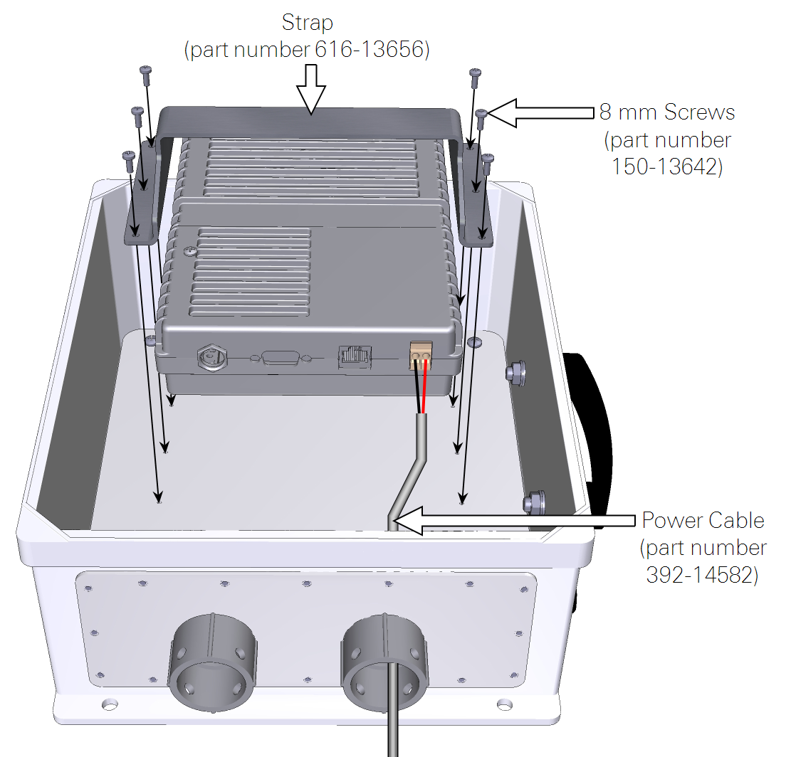
- Assemble the system.
- Install the power cable first because it is difficult to access the connectors after the terminal in installed in the enclosure. Mount the terminal in the enclosure as shown.
- Install the Ethernet data cable and antenna cable.
- A long, weatherproof Ethernet cable (part number 392-13977 for the LI-7550) connects the terminal to the LI-7550 or LI-8100A Ethernet port.
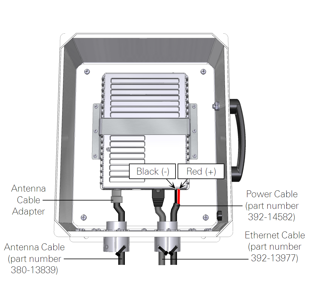
- Mount the enclosure, antenna, and antenna cable.
- The antenna cable is a slender coaxial cable. Tighten both cable connections securely. Mount the antenna to a tripod or mast so it has adequate reception from the wireless service provider. Be sure that the antenna placement does not obstruct the wind or alter any of the variables that are measured at the site (see Mounting the antenna).
Mounting the communication enclosure
The enclosure mounts on a tripod, tower, or post with two mounting brackets (part number 9979-022). It should be mounted at the base of the tower, away from instruments. Cables should be secured so that strain is not applied to the cable or connectors and to avoid sharp bends in the cables.
The mounting brackets and band clamps accommodate a mounting post of up to 7 cm (2.75 inches) in diameter. Hardware is included to attach the mounting plates to the enclosure. Band clamp brackets should be attached to the mounting plates, and then the band clamps can be inserted through the holes in the brackets and tightened around the post, as shown in Figure 2‑1.
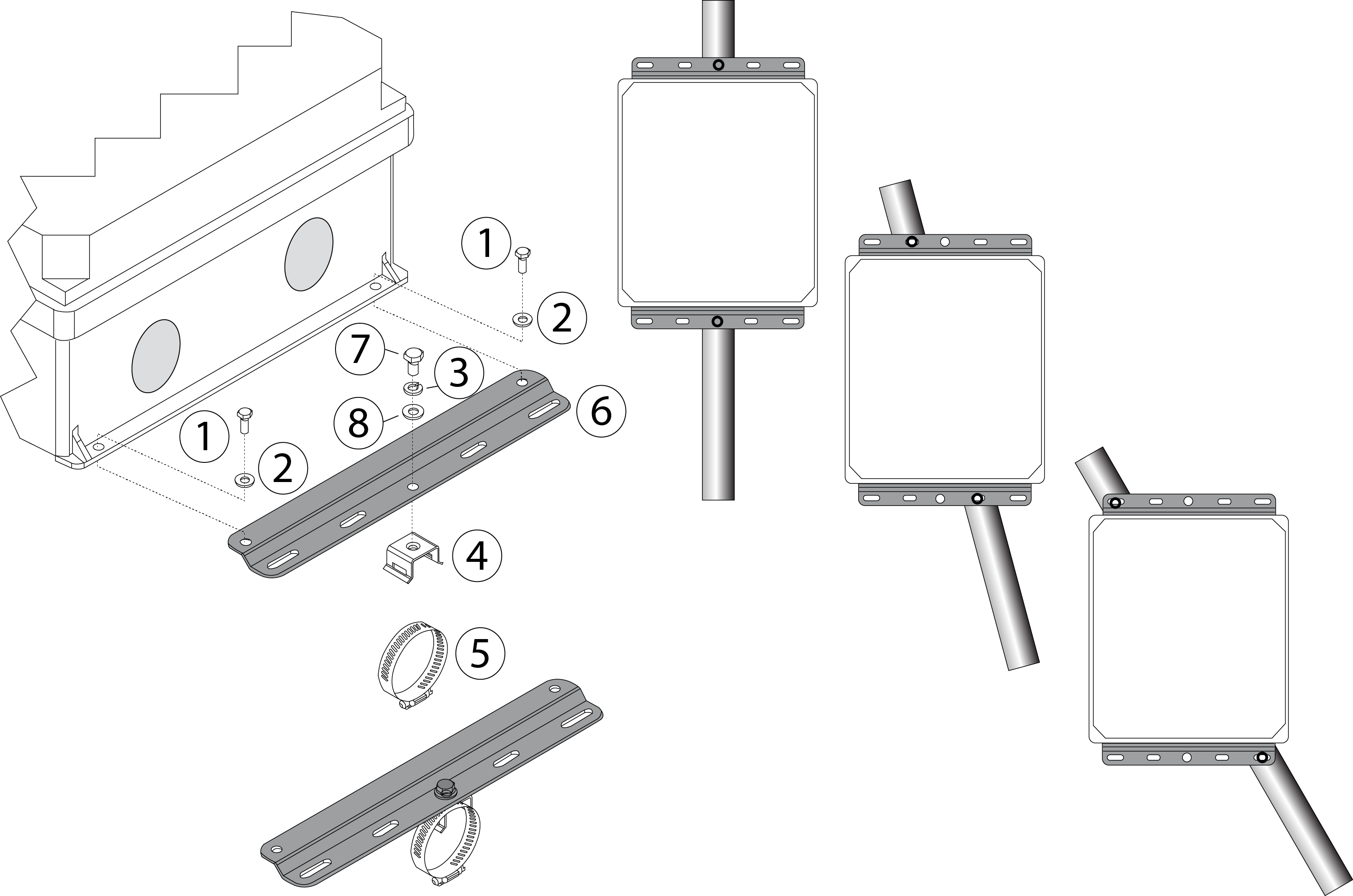
| Item | Qty. | Part Number | Description |
|---|---|---|---|
| 1 | 4 | 150-12943 | M6x1 × 16 MM Hex Head Bolt |
| 2 | 4 | 167-02054 | Flat Washer 1/4 x 5/8” |
| 3 | 2 | 167-05635 | Split Washer 5/16” |
| 4 | 2 | 235-13234 | Band Clap Bracket |
| 5 | 2 | 300-13293 | Band Clamp, 9/16” |
| 6 | 2 | 9879-045 | 26 cm Mounting Plate |
| 7 | 2 | included w/ item #4 | 5/16-24 × 1/2” Hex Head Bolt |
| 8 | 2 | included w/ item #4 | 5/16” Flat Washer |
Mounting the antenna
Warning: Maintain at least 20 cm separation distance between the antenna and your body when the terminal is powered on. Do not stand in front of the antenna or place your head or body parts in front of the antenna when the system is operational.
Position the antenna so that it has clear reception and does not interfere with the variables you are measuring. Be sure it does not shadow any radiation sensors, obstruct the rain gauge, or obstruct eddies in an eddy covariance system.
Important: The antenna is a transmitter/receiver that broadcasts electromagnetic radio signals. Some electronic devices, data recorders, and sensors may be susceptible to radio interference from this antenna. Therefore, it is important to position the antenna at a reasonable distance from sensors and data recorders. Never put the antenna in an instrument enclosure, adjacent to instruments on your instrument platform, or pointing toward instruments or cables. Maximize the distance between instruments and the antenna using the provided 15 m cable to reduce the chance of radio interference.
- Before you dig!
- Check to ensure that there are no underground gas lines, electrical lines, or unexploded ordnance in the vicinity.
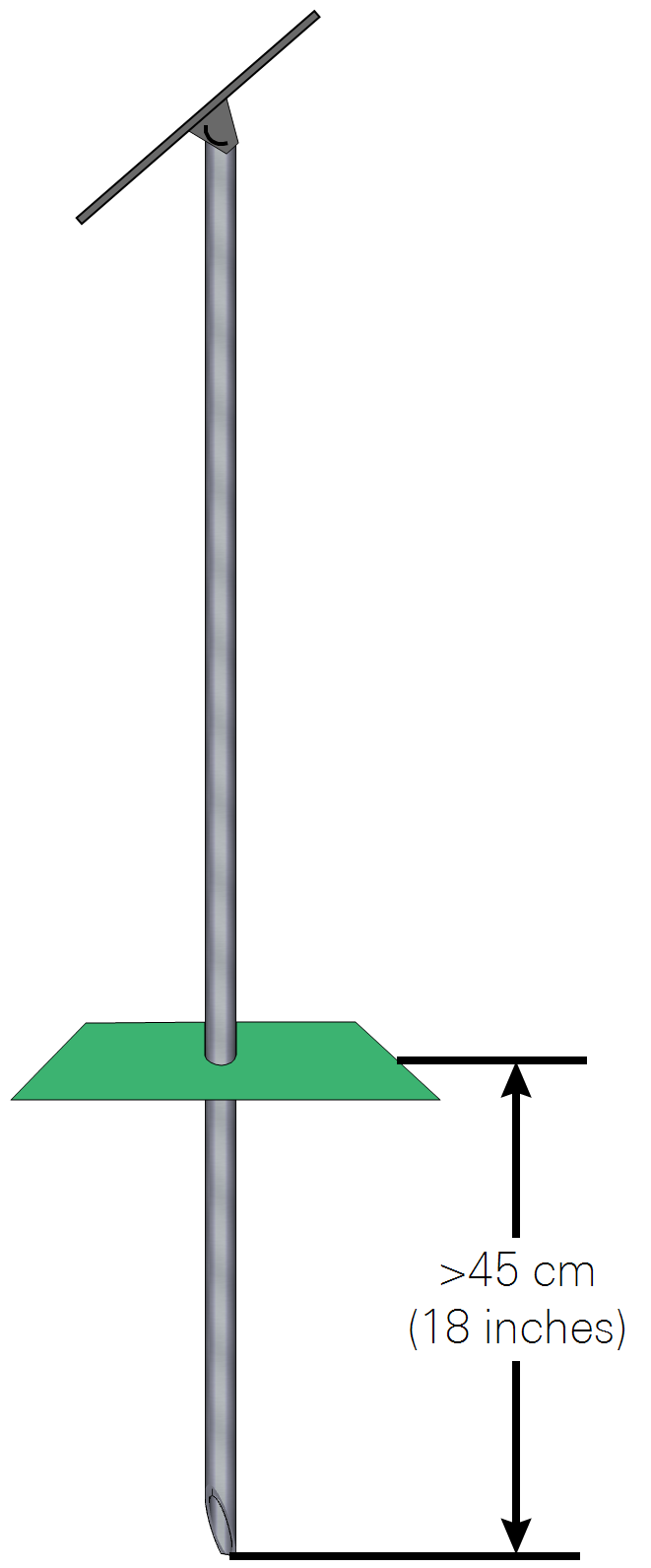
- Drive the antenna mounting post.
- Drive the post at least 18 inches (0.5 m) into the ground and attach the antenna using the included bracket and band clamp. In sandy, muddy, or loose soils additional support may be required to secure the mounting post.
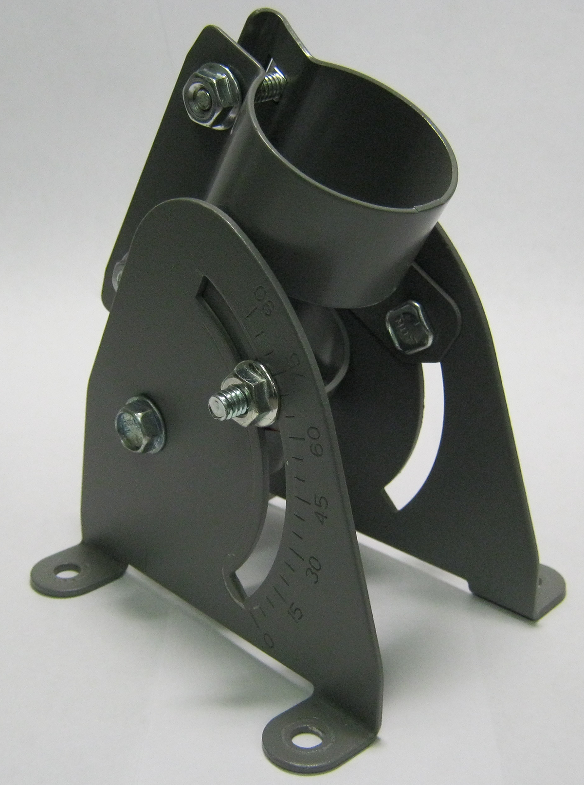
- Install the Azimuth/Elevation Bracket on the antenna.
- Then install the antenna as shown in Figure 2‑3.
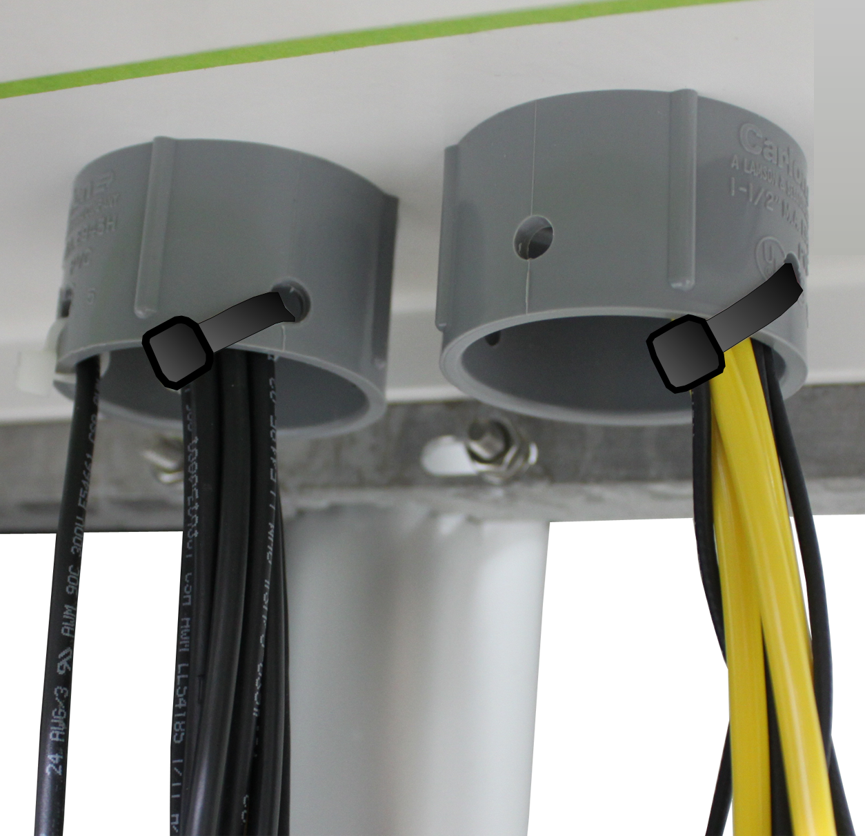
Securing cables
Communication and power cables should be secured so they do not apply strain to connectors and junctions. Secure the cables to the strain-relief plugs as shown.