Maintenance
This section describes typical maintenance procedures for the LI-600. For many of these procedures, support videos are available at licor.com/support/LI-600/videos.html.
Storing the LI-600
Follow these guidelines when storing the LI-600.
- Power down and store it in the carrying case when not in use; this will keep dust, insects, and other contaminants out of the aperture.
- Store it in a climate-controlled environment.
- Charge the battery to 60% capacity prior to long-term storage.
- Disconnect the power supply.
Cleaning the LI-600
These are basic cleaning procedures for the exterior components of the LI-600.
Caution: Always turn off the LI-600 before cleaning.
Barcode window and quantum sensor
Regularly check that the barcode window and quantum sensor are clean, as dirt and debris may accumulate after active use.
Use a foam swab and deionized water to clean the quantum sensor and barcode window. Use the microfiber cloth to dry the surface if necessary.
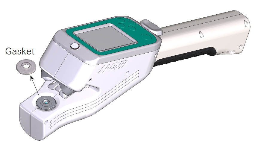
Clamp and gasket
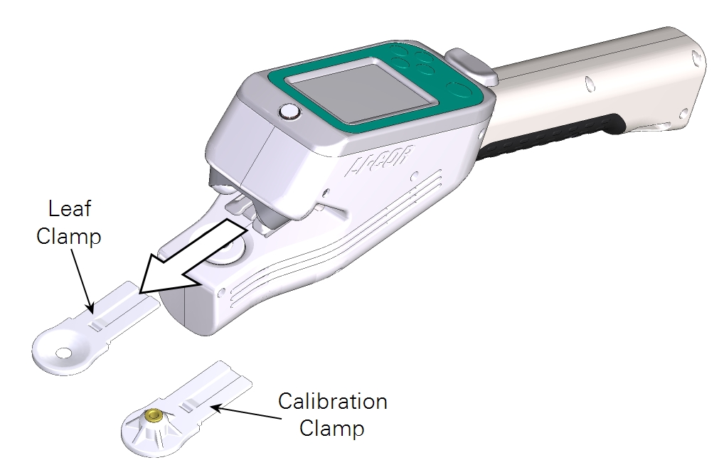
To clean the clamp and gasket, first remove them. Remove the clamp by pulling it straight out. The gasket can be gently pried and pulled off from its edge using a fingernail or toothpick. Do not clean the gasket while it is on the instrument.

Use foam swabs and deionized water to carefully clean the clamp window. Do not use soap on the window.
If dirt remains on the leaf gasket, gently wash it in water and a mild detergent and completely dry it before reinserting. If needed, replace it with a new gasket (included in the accessories kit, part number 6360-356).
Note: Prevent water from entering the cuvette. Water can damage sensitive components. If water enters the cuvette, disassemble the instrument and remove the water using a foam swab.
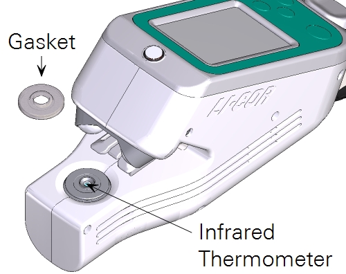
Infrared thermometer
Check that the infrared thermometer is clean after periods of heavy use, or before or after long-term storage. A dirty infrared thermometer will throw off tleaf values.
- Power off the instrument.
- Remove the leaf clamp (pull straight out).
- Remove the aperture gasket by lifting one edge and peeling it from the aperture.
- Use a foam swab and isopropyl alcohol to carefully clean the sensor.
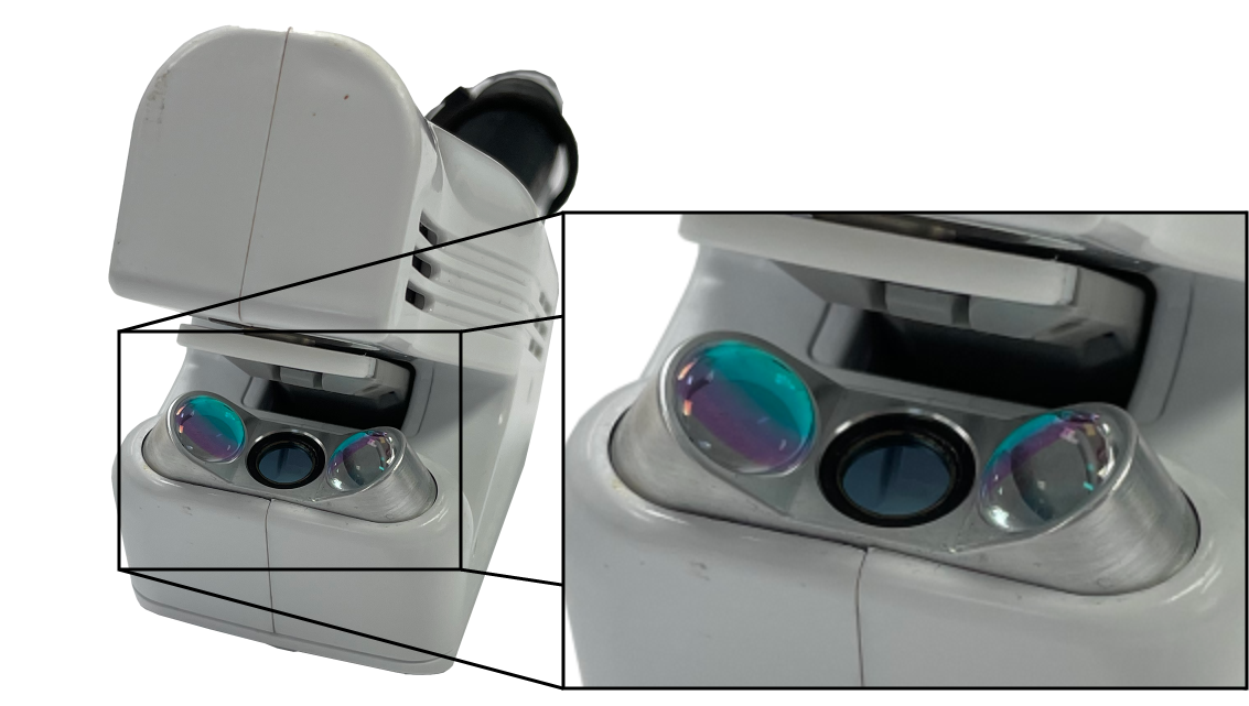
Fluorometer
Regularly check that the fluorometer LEDs and fluorescence detector are clean. Use foam swabs, a microfiber cloth, and isopropyl alcohol to carefully clean the fluorometer optics.
Removing the instrument shells
Work indoors in a clean environment when removing the instrument shells. Use a #1 Philips screwdriver to remove the screws.
- Remove seven screws on the left side of the instrument.
- Remove five screws on the right of the instrument.
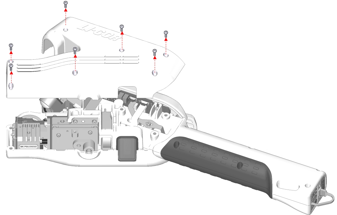
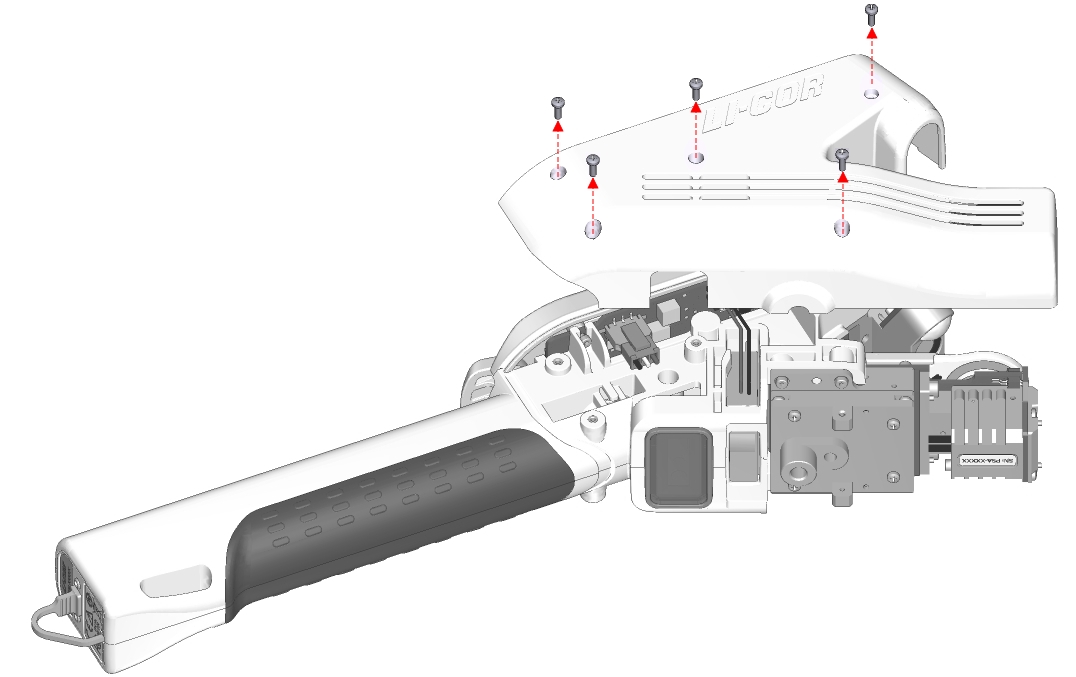
Reassembly is the reverse of removal.
Cleaning the shell vents
Check that the four vents on the instrument head shells are clean. With the shells removed, use compressed air to carefully clean the vents and other enclosure parts.
Cleaning the RH sensors
Regularly check that the RH sensors are clean, for example after a campaign, before extended storage, or if a shift in ambient RH is noted.
- Use a squeeze bottle with deionized water to carefully rinse the RH sensors.
- Do not touch the active side of the sensors with your fingers or a swab. Do not use isopropyl alcohol.
- Dry them with compressed air, then bake them for 6 hours at 100 to 120 °C.
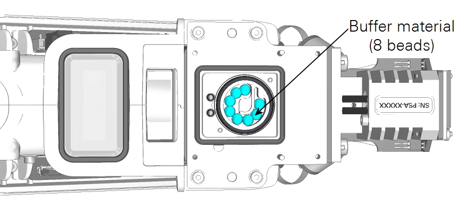
Never touch the RH sensors or H2O buffer material in the instrument head, as oils on the skin and scratches can affect the instrument’s performance.
Removing and inserting a battery
Removing and inserting the battery is only required when the battery no longer functions and needs replacement.
- Power off the instrument and ground yourself to avoid potential electrostatic discharge.
- Remove the shells.
- Remove the shells on the instrument head. Set the shells safely aside.
- Unplug the battery connector.
- On the right side of the instrument head, locate the cable clip. Push down on the clip and disconnect the battery connector.
- Remove the coverings on the instrument handle.
- Remove the six screws nearest the USB port on the handle using a Phillips screwdriver; do not remove the two hex screws at the end of the handle. Gently spread apart the left and right handle coverings but do not remove completely.
- Detach the endcap.
- The dust cap may dislodge while removing the endcap. Set both safely aside.
- Remove the old battery.
- To the right of the connector slot, ease the wires out from behind the tab. Gently remove the old battery from the handle, guiding the battery connector out through the connector slot in the instrument head.
- Insert the new battery.
- Gently insert the new battery into the handle, guiding the battery connector in through the connector slot in the instrument head. Place the wires behind the tab.
- Replace all parts in reverse order.
- Replace the dust cap, endcap, and instrument handle coverings. Plug in the battery connector and replace the instrument head shells.
After a battery replacement or any other repair, verify the safe state of the instrument by checking that the display and the fan are powered off.
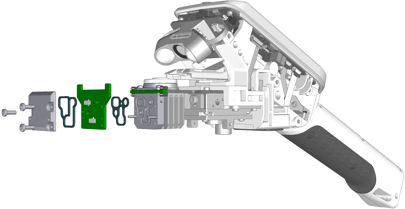
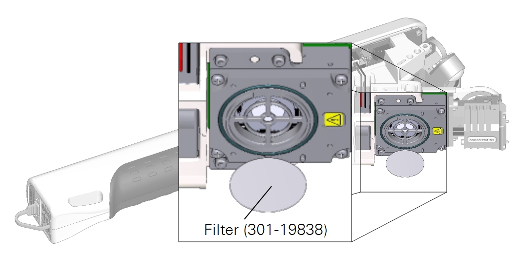
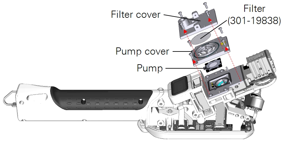
Replacing the air intake filter
The air intake filter serves to remove solid particles from air before it is drawn through the LI-600 porometry system. A 0.45 micron filter (part number 301-19838) is a direct replacement for the original 1.0 micron filter (part number 301-16918).
Follow these steps to replace the air intake filter.
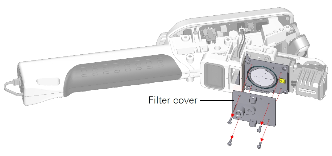
- Remove the shells.
- Remove the filter cover.
- Remove the filter using gloves or tweezers.
- Install the replacement filter from the accessories kit.
- Always use gloves or tweezers, as oils on the skin and scratches can damage the filter.
- Replace the filter cover and instrument head shells.
Calibrating the sensors
The LI-600 includes sensors whose calibration parameters can be adjusted by the user: relative humidity (RH) sensors, flow sensors, and a fluorescence detector. This section describes the process of setting the available parameters for each sensor.
To view user calibration coefficients and change the user-adjustable parameters, connect the LI-600 to the computer software. In the drop-down menu on the Toolbar, select Instrument Calibration. (For sensor equations, see Theory of operation)
All calibration coefficients can be viewed in Factory Calibration if enabled in the software Preferences. See Drop-down menu.
RH sensors
RH sensor parameters include Zero, or the sensor’s response to dry air, and Span, or the sensor’s response to a known dew point or H2O mole fraction.
Using the LI-600 pump
Take the following steps to dry the RH sensors using the internal pump and zero kit.
- Power off the LI-600.
- Remove the shells (see Removing the instrument shells).
- Remove the filter cover and filter.
- The H2O buffer material is in the flow path and must be removed to zero the RH sensors. Remove the filter cover and filter using gloves or tweezers.
- Remove the pump cover and pump.
- Remove the four screws on the pump cover then remove it. Using gloves, remove the pump to gain access to the H2O buffer material. The pump part number is 286-17946.
- Handle the black plastic corners only.
- Remove the H2O buffer material.
- Use gloves or tweezers to remove the H2O buffer material, as oils on the skin and scratches can reduce its buffering efficacy.
- Alternatively, turn the LI-600 over a container to collect the H2O buffer material.
- Reinstall the filter cover, filter, pump cover, and pump.
- Reinstall the parts with the H2O buffer material removed.
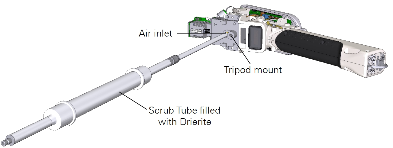
- Connect the zero kit.
- Attach the zero kit to the air inlet next to the tripod mount via the 10-32 fitting.
- Seal the leaf aperture.
- To seal the leaf aperture, clamp on a plastic bag or similar material.
- Open Instrument Calibration.
- Power on the LI-600. Connect it to a computer via USB then open the computer software. Click the drop-down menu on the Toolbar then select Instrument Calibration.
- Power on the internal pump.
- Select RH Zero then click Begin RH Zero Calibration to view the RH Ref and RH Sample. Click TURN PUMP ON.
- Dry the RH sensors.
- Wait for RH to stabilize at ±1% then select Zero in the computer software. If trending down, zeroing is not required.
- Ensure that the chemicals are fresh, such as Drierite® (P/N 622-10509), to provide a low dew point.
- Reinstall all parts in reverse order.
- Reinstall the H2O buffer material, pump, pump cover, filter, filter cover, and instrument head shells.
Using a user-supplied airstream
Follow these steps when drying the RH sensors using a user-supplied airstream from an air tank. Alternatively, you can use a user-supplied pump and the zero kit (P/N 9968-258) with chemicals to dry the RH sensors. If using an external pump with the zero kit, ensure that the chemicals are fresh, such as Drierite, to provide a low dew point.
Using an airstream in the RH sensor zeroing process requires the least disassembly.
- Prepare the LI-600.
- Power on the instrument.
- Open Instrument Calibration.
- Connect the LI-600 to a computer via USB then open the computer software. Click the drop-down menu on the Toolbar then select Instrument Calibration.
- Power off the pump.
- Select RH Zero then click Begin RH Zero Calibration to view the RH Ref and RH Sample. Click TURN PUMP OFF.
- Remove the leaf clamp.
- Gently but firmly pull on the leaf clamp to remove it from the instrument.
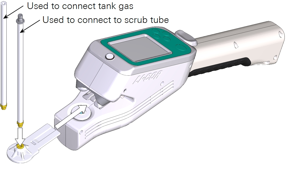
- Attach the calibration clamp.
- Gently but firmly attach the calibration clamp. The calibration clamp is equipped with a 10-32 hose barb for tube connection (9960-327).
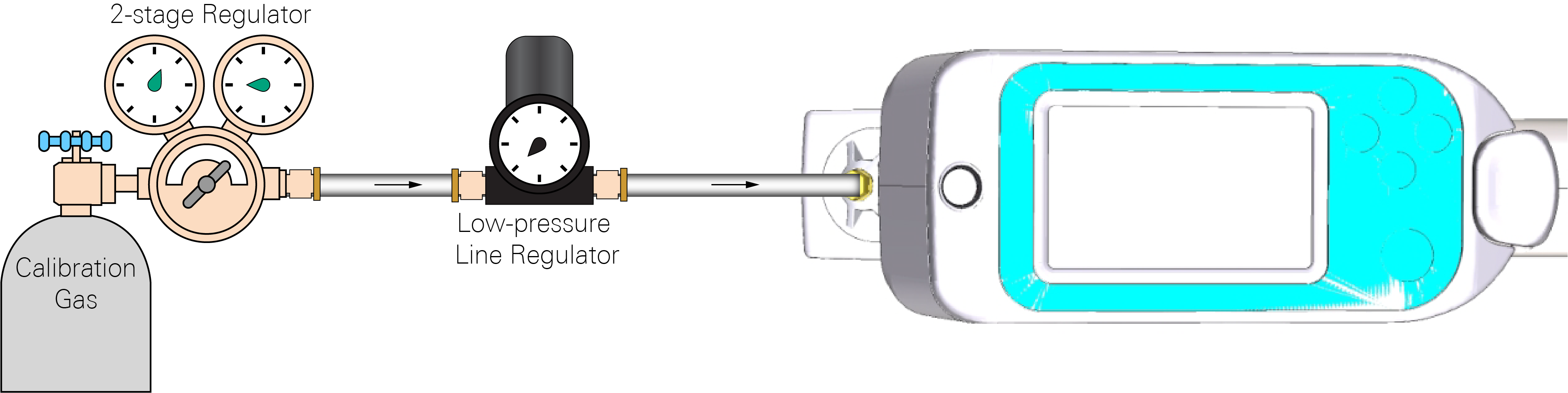
- Attach the air tank.
- Connect a tank of ultrapure dry air to the calibration clamp, ensuring that the tube connection does not prevent the clamp from sealing properly.
- Dry the RH sensors.
- Deliver an airstream across the RH sensors for 30 minutes to 1 hour. Do not allow maximum airflow to exceed 0.25 LPM. The flow or inlet flow sensor will read negative values (i.e., approximately -30 to -100 µmol s-1) due to the air flow toward both the air exhaust and air inlet. Flow_s will read positive values (i.e., approximately 100 to 200 µmol s-1).
RH sensor zero
Follow these steps when zeroing the RH sensors.
- Pump for drying the RH sensors.
- Proper drying of the RH sensors can take up to 30 minutes, as water adheres to all surfaces in the flow path. This ensures that no water remains in the system.
- Dry the sensors using one of two methods: using user-supplied airstream or using the LI-600 pump. If drying the sensors by delivering an airstream across the sensors using either a tank of dry gas (recommended) or an alternate airstream method, see Using a user-supplied airstream. If delivering airflow across the sensors via the LI-600 pump only, see Using the LI-600 pump. If the resulting RH is <1% and trending down after several minutes, the zero does not require resetting.
- Open Instrument Calibration.
- Connect the LI-600 to a computer via USB then open the computer software. Click the drop-down menu on the Toolbar then select Instrument Calibration.
- Power off the pump and power on the blower.
- Select RH Zero then click Begin RH Zero Calibration to view the RH Ref and RH Sample. Click TURN PUMP OFF then click TURN BLOWER ON.
- Zero the RH sensors.
- When the RH stabilizes, click Zero for RH Ref then again on the confirmation prompt to reset the zero. Click Apply on the second confirmation prompt to finish. Repeat for RH Sample.
RH sensor span
A known H2O input is required to span the RH sensors using another H2O analyzer or a dew point generator. Take the following steps to span the RH sensors.
- Prepare the LI-600.
- Power on the instrument.
- Open Instrument Calibration.
- Connect the LI-600 to a computer via USB then open the computer software. Click the drop-down menu on the Toolbar then select Instrument Calibration.
- Set the H2O input.
- Select RH Span then click Begin RH Span Calibration to view the RH Ref and RH Sample. Select either Dew Point or Mole Fraction then enter the desired H2O input.
- Power off the pump.
- Select Utility then click TURN PUMP OFF.
- Remove the leaf clamp.
- Gently but firmly pull on the leaf clamp to remove it from the instrument.
- Attach the calibration clamp.
- Gently but firmly attach the calibration clamp. The calibration clamp is equipped with a 10-32 hose barb for tube connection.
- Attach the dew point generator.
- Connect a dew point generator to the calibration clamp, ensuring that the tube connection does not prevent the clamp from sealing properly.
- Span the RH sensors.
- Deliver an airstream across the RH sensors then click Span in the computer software when they stabilize, which can take approximately 30 minutes. Do not allow maximum airflow to exceed 0.25 LPM. The Flow or inlet flow sensor will read negative values (i.e., approximately -30 to -100 µmol s-1) due to the airflow toward both the air exhaust and air inlet. Flow_s will read positive values (i.e., approximately 100 to 200 µmol s-1).
Flow sensors
The flow sensors’ response to no active flow can alter over time and can be reset. Take the following steps to reset the flow sensors. No disassembly is required.
- Open Instrument Calibration.
- Connect the LI-600 to a computer via USB then open the computer software. Click the drop-down menu on the Toolbar then select Instrument Calibration.
- Power off the pump and blower.
- Select Flow Zero then click Begin Flow Zero Calibration to view Flow In Zero and Flow Out Zero. Click TURN PUMP OFF then click TURN BLOWER OFF.
- Zero the flow sensors.
- When Flow In Zero and Flow Out Zero stabilize, click Zero for Flow In Zero then again on the confirmation prompt to reset the zero. Click Apply on the second confirmation prompt to finish. Repeat for Flow Out Zero. If Flow In Zero stabilizes at ±1 or Flow Out Zero at ±5, the zero does not require resetting.
Fluorescence detector
The fluorescence detector can be reset to remove any offsets in the detector electronics. Take the following steps to reset the fluorescence detector.
- Open Instrument Calibration.
- Connect the LI-600 to a computer via USB then open the computer software. Click the drop-down menu on the Toolbar then select Instrument Calibration.
- Check the fluorometer response.
- Select FLR Zero then click Begin FLR Zero Calibration to view FLR Zero. Click Zero then ensure that the Flr Response with an empty cuvette is approximately ±5 units.
- Zero the fluorescence detector.
- If Flr response is not approximately ±5 units, click Zero to reset the zero for the fluorescence detector.
Changing the RH sensors serial number
The RH sensors board can be user replaced. However, the RH sensors serial number does not automatically update and must be updated in the computer software to obtain the correct calibration information. If a new RH sensors board is installed without updating the serial number, the LI-600 will continue logging data using the old sensor serial number.
Take the following steps to change the RH sensors serial number.
-
Connect the LI-600 to a computer via USB then open the computer software.
In Explore the LI-600, open the drop-down menu and select Preferences.
-
Check the Allow Factory Calibration box then click Close.
Select the drop-down menu again to allow the software to register the change then click Factory Calibration.
-
Select RH under Factory Calibration then click Calibrate. Click OK on the confirmation prompt.
The Change RH Sensor Serial Number and Automatic RH Sensor Calibration buttons will appear. Click Change RH Sensor Serial Number then input the serial number.
-
Click OK on the confirmation prompt.
-
Click Automatic RH Sensor Calibration to calibrate the RH sensor.