
Printable PDF: Installing the small leaf chamber
(6800_InstallGuide_Clear-top_Leaf_Chamber_16138.pdf)
Download this content as a pdf that can be saved to your computer or printed.
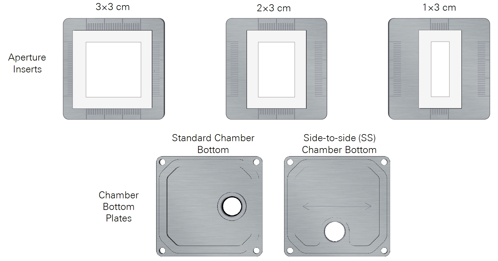
The clear-top chamber is used to measure small leaves. The 6800-12A model features removable aperture inserts that reduce the area of leaf in the chamber. The apertures are 3×3 cm, 2×3 cm, and 1×3 cm. The 2×3 cm and 1×3 cm apertures can be installed with the opening side-to-side or front-to-back. Here we describe how to use the chamber and apertures.
You also may be interested in Installing the large leaf chamber or Installing the fluorometer chamber. See Removing a chamber to detach a chamber.
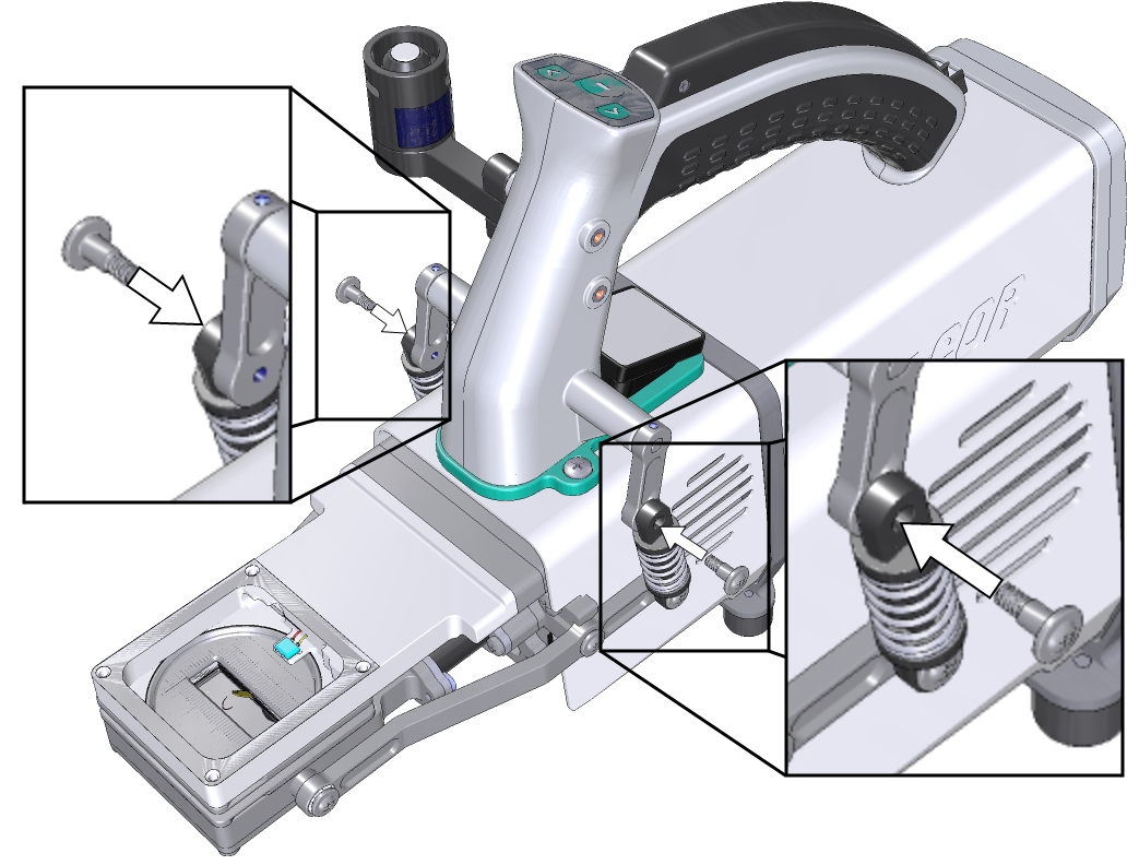
- Hold the chamber in position, with the spring closest to the cooling fan facing up toward the handle, and tighten the two captive chamber mounting screws (144-15344).
- Use the #2 Phillips screwdriver from the spares kit. Suitable screwdrivers are available from most departments stores.
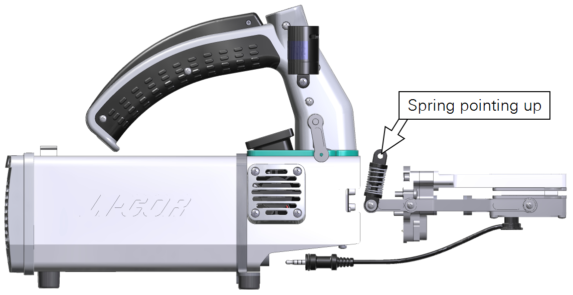
- Caution: Use the captive chamber mounting screws to install the chamber. Other screws will cause leaks and problems with the mixing fan.
- Make them snug—turn each screw until it stops, and then just a little bit more (up to ¼ turn). If you have a torque screwdriver, tighten them to 2.5 N·m (22 inch lbs).
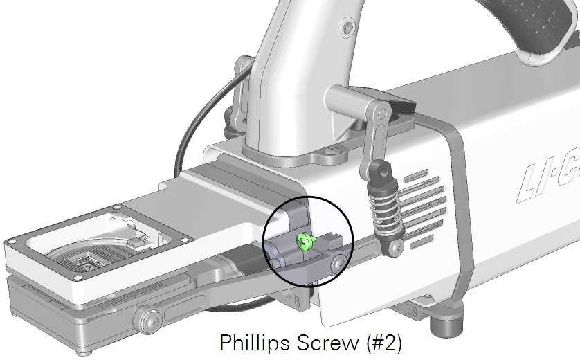
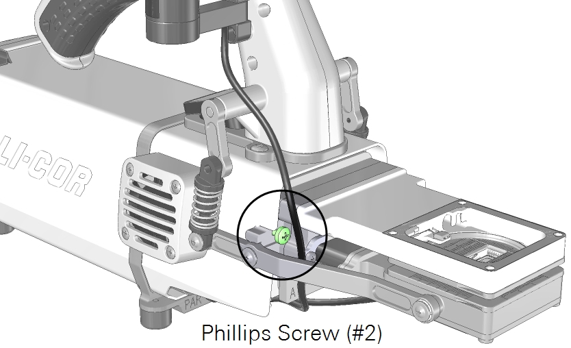
- Install the latch screws.
- With the latch in the parked position, tighten the screws until they are snug. If you have a torque screwdriver, tighten them to 1.1 N·m (9.4 inch lbs). Double check the tightness of each screw.
- Install the light sensor connector to the connection labeled PAR.
- Install the leaf chamber apertures and the corresponding chamber bottom plate.
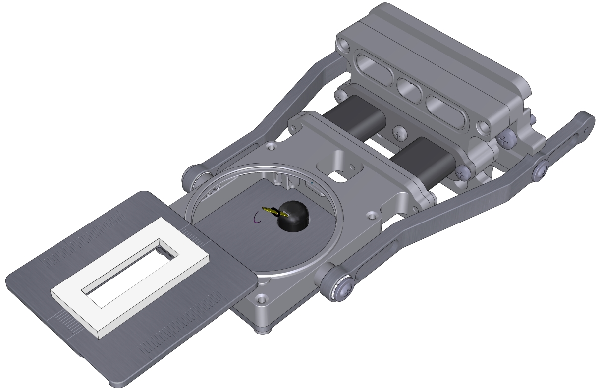
- Install the leaf temperature thermocouple and attach the connector to the connection labeled T1.
- Check the thermocouple height and adjust if necessary.
- Install the connector cover.
After swapping chambers or apertures, it is a good idea to run the leak test (under Start up > System Tests > Chamber Leak). Check to see that the chamber is recognized under Constants > System Constants > ChType.
Using apertures
The clear-top chamber (6800-12A) includes removable chamber apertures that allow you to reduce the exposed leaf area chamber. Three sizes of apertures are included. There are two chamber bottom plates that allow you to position the leaf temperature thermocouple correctly.
Points to remember
- Top and bottom chambers must be the same size and have the same orientation. For example, do not use the 2×3 cm upper aperture with a 1×3 cm lower aperture or a 2×3 cm upper chamber oriented front-to-back (FB) to the head and a 2×3 cm lower chamber oriented side-to-side (SS) to the head.
- With the 1×3 cm aperture opening oriented side-to-side, use the side-to-side chamber bottom plate. This bottom plate positions the leaf thermocouple so it makes contact with the leaf.
- When you install apertures, select the correct aperture in the software in order to use the correct leaf area and other parameters in computations. You can correct the leaf area and recompute your data later, but it is always a good idea to get the settings right from the outset.
Swapping apertures
Apertures press into the chamber and are held in place by the O-ring.
- Remove both upper and lower apertures.
- Insert a coin into the slot and pop the aperture out.
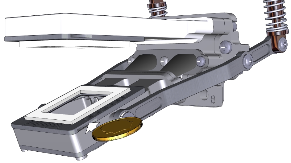
- Align the desired apertures and press each one firmly into the chamber.
- If using foam gaskets, the white gasket goes into the upper chamber and the black gasket goes into the lower chamber.
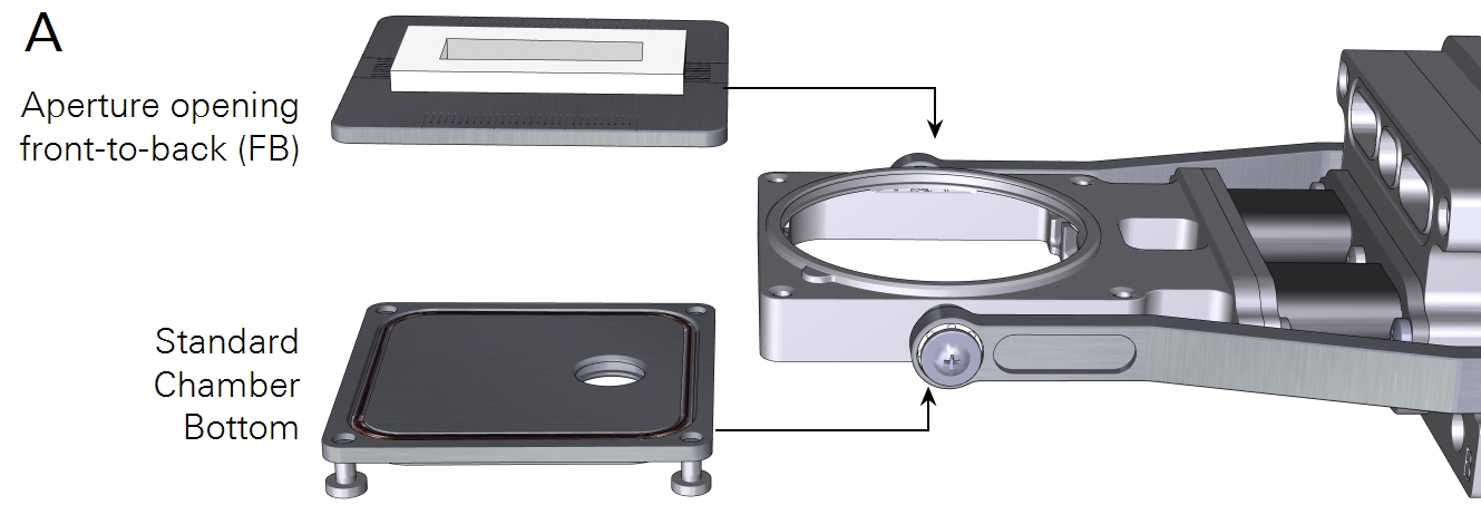
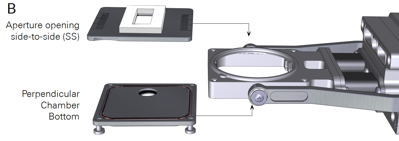
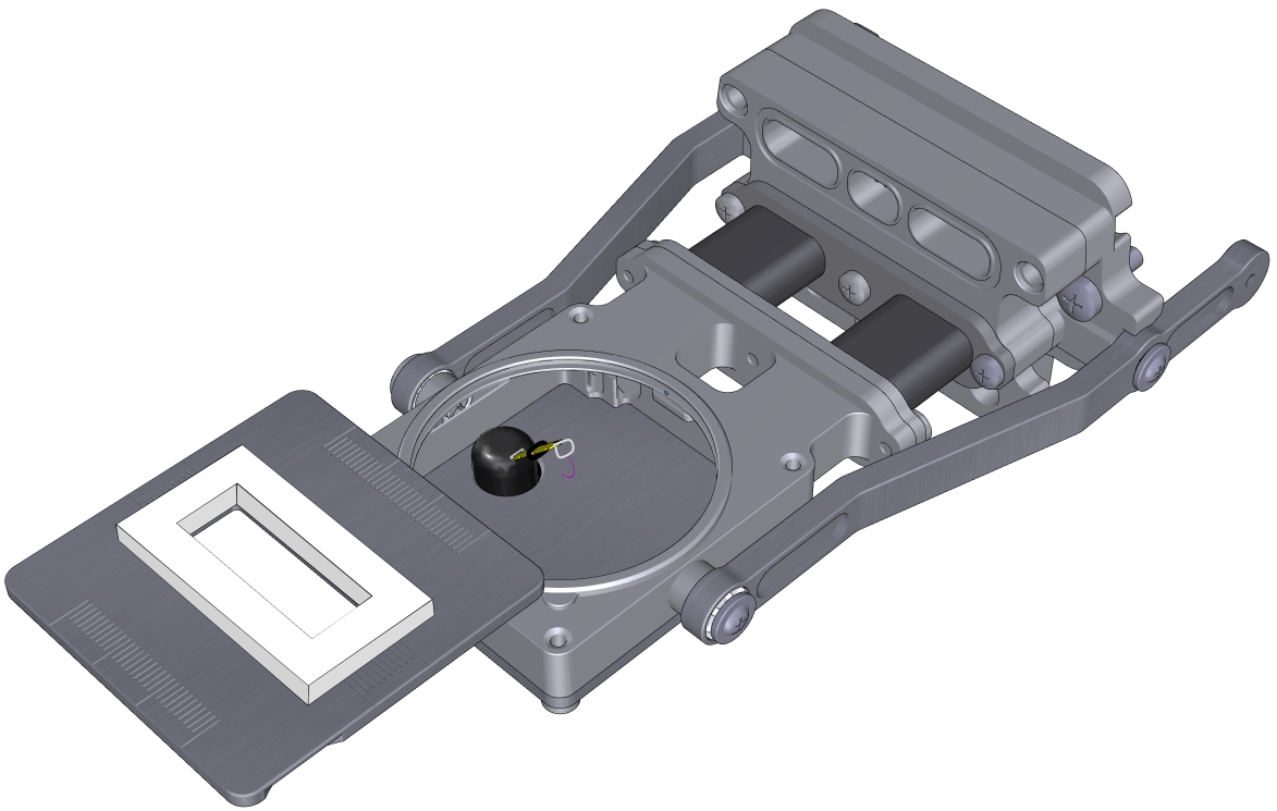
- If you are using the 1×3 cm aperture aligned side-to-side to the head, install the perpendicular chamber bottom plate as shown in B in Figure 9‑14.
- Install the leaf temperature thermocouple.
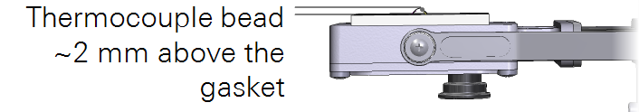
- Adjust the height and orientation as needed to maintain good contact with the leaf. 2 mm above the gasket is ideal for most leaves.
- Plug in the temperature connector into the T1 or T2 connector on the head.
- Power on the LI-6800 and let it warm up.
- Select the aperture size and orientation.
- Even though the chamber itself is recognized by the LI-6800, you will have to specify which aperture is in use. Under Start Up > Chambers, select the aperture and its orientation.
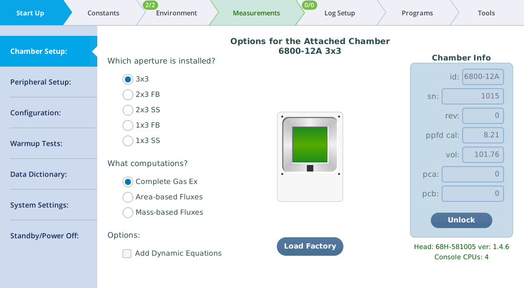
- The images on the display will help you understand which setting is which.
- 3×3: Standard aperture
- 2×3 FB: 2×3 cm aperture oriented front-to-back
- 2×3 SS: 2×3 cm aperture oriented side-to-side
- 1×3 FB: 1×3 cm aperture oriented front-to-back
- 1×3 SS: 1×3 cm aperture oriented side-to-side
Connecting the small light source
The 3×3 cm light source attaches directly on top of the 3×3 cm small leaf chamber.
 Warning: The light sources for this product can emit potentially hazardous optical radiation (RG-2 CAUTION POSSIBLY HAZARDOUS OPTICAL RADIATION EMITTED FROM THIS PRODUCT), in excess of the Exempt Risk Group. Potential risk depends upon how one uses and installs this product. Do not operate the light source while detached from the chamber. Do not look directly into the light source under any circumstances. Operate the light sources with direct access to ambient air for cooling. Do not use the product in any manner not described in the manual.
The light source mounts directly onto the chamber.
- Check the chamber top Propafilm for dirt or damage.
- Clean or replace it if necessary.
- Check the light source window for smudges or fingerprints.
- Wipe it with a soft cloth or alcohol swab if necessary.
- Position the light source over the chamber, then tighten the two screws.
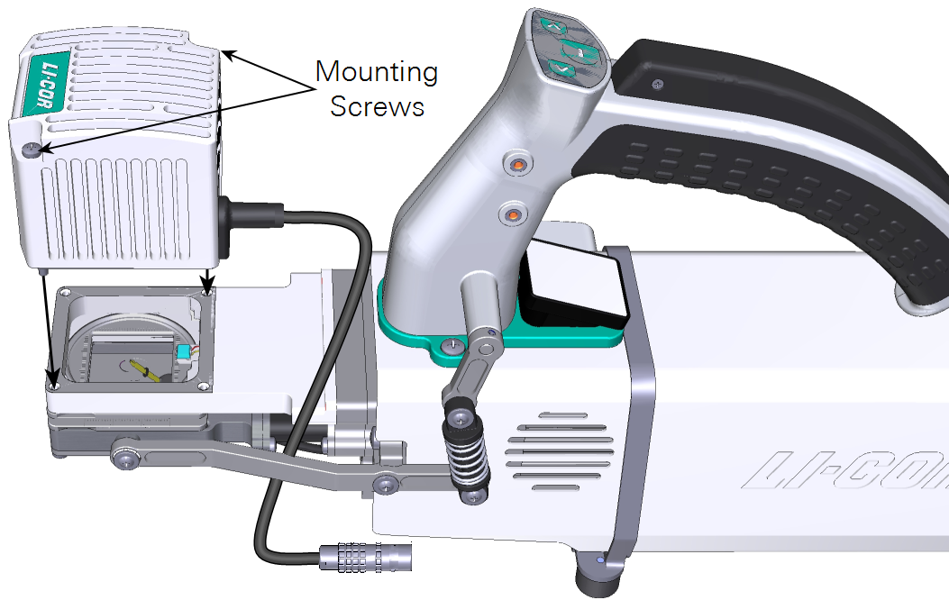
- Tighten them snugly—until the screw stops, then just a little bit more (up to ¼ turn).
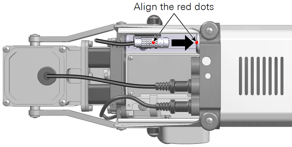
- Plug in the cable connector.
- Remove the connector cover from the bottom of the head, then route the cable between the chamber arm and duct. It connects to the light source connecter (labeled LS) under the connector cover. Align the red dot on the connector with the red dot on the connection.
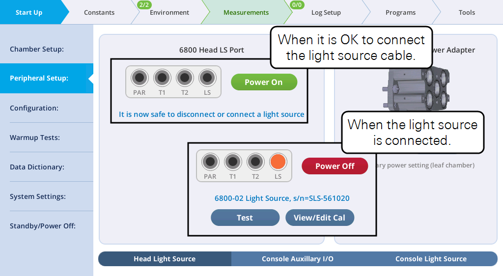
- Check the light source under Start Up > Peripheral Setup > Head Light Source. The instrument should detect the light source and power it on automatically a few seconds after it is connected.
- Check the response.
- Under Environment > Light > Head LS, set Head LS to On, and set the Q Setpoint to 200 µmol m-2 s-1. Open the chamber and look at the light that shines onto the chamber bottom (never look directly into the light sources).
- If this is your first time using the light source, Set Color Ratio to Red: 0 and Blue: 1. You should see blue light. Then switch to Red: 1 and Blue: 0. You should see red light. Then set Red: 9 and Blue: 1 to provide 9 parts red and 1 part blue, which is a typical ratio for gas exchange measurements.