Initial configuration
The LI-7500DS Windows software is used to configure the instrument. Go to licor.com/support/LI-7500DS/software.html for the latest version and install it on your computer. Download embedded firmware and interface software for all components in the system. We recommend using the latest software for the best performance.
1. Power on the system
With all of the wire leads and data cables connected as described in Initial assembly, you are ready to power on the system. Provide power (12 or 24 VDC; 4 to 5 amps) to the system enclosure terminals, then turn the breakers to the ON position. Allow several minutes for the instruments to start up then check the LEDs:
- DSI box: Power and Status LEDs solid.
- SmartFlux System: Power IN LED solid; Status LED slow blink when ready.
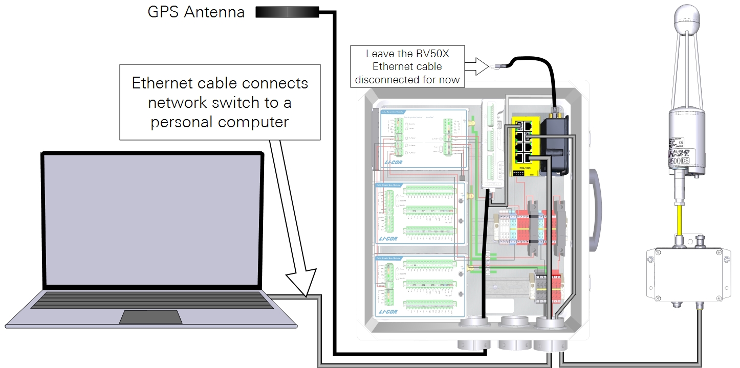
2. Install an Ethernet cable between the system and a computer
A standard Ethernet cable (616-06116) can be connected between a computer and the network switch.
3. Connect with the SmartFlux 3 System
Launch the application (called LI-7x00 A RS DS 8.x), select the SmartFlux 3 System from the list, and click Connect.

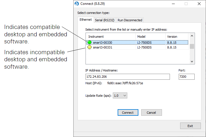
- If there is a yellow dot beside the instrument (
 ), update the firmware as described in Software updates.
 - If you are connecting the instrument to an RV50X cellular gateway, set the IP address as described in the RV50X instruction manual from LI-COR.
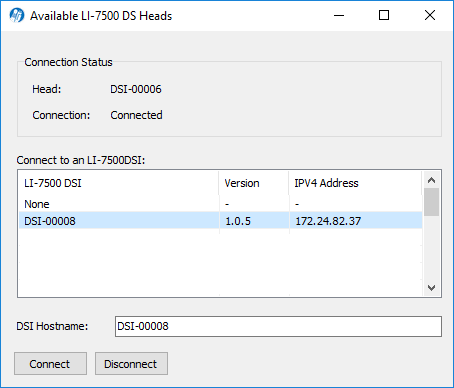
4. Establish the connection between SmartFlux and the LI-7500DS
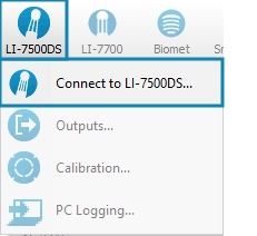
If the window does not open automatically, click LI-7500DS > Connect to LI-7500DS. Select the instrument by serial number and click Connect.
5. Configure the gas analyzer
Proceed through the steps in Configuring the gas analyzer.
6. Connect with accessory components
If you are using an LI-7700, a Biomet Data Acquisition System, PhenoCam, LI-8100A, FluxSuite, or an RV50X cellular communication system, additional settings must be configured. See Additional eddy covariance options.
7. Configure the eddy covariance system
Some of the required information is determined by the site characteristics and instrument arrangement (see Collect data on the setup). The remaining steps for a basic eddy covariance system are taken in the gas analyzer PC software (see Configuring the eddy covariance system).
Important: Some settings are required for the SmartFlux System to proceed with calculations. If you do not enter this information or enter it incorrectly, EddyPro on the SmartFlux System will not calculate fluxes or will compute incorrect results. Required fields are marked as mandatory.
The SmartFlux System uses EddyPro express settings by default. If you want to use advanced processing, additional steps must be taken to configure the system. See EddyPro processing on the SmartFlux System for more information about Express and Advanced modes.
Configuring the gas analyzer
These settings are related to the system clock, the operating temperature range, and the instrument bandwidth.
Setting the system clock
Under Settings > Time, two settings must be configured: Time Zone and Clock Sync (PTP).

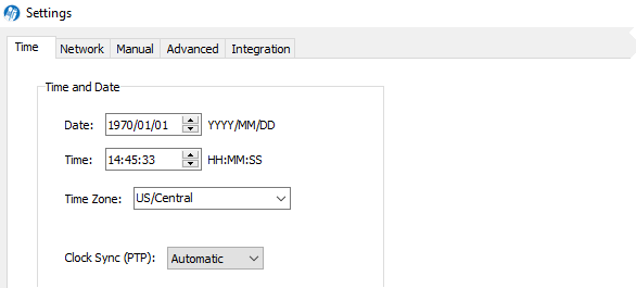
- Time Zone: Select the time zone to use for the site. If the location observes daylight savings time, choose an offset from Etc/GMT to avoid overwriting or creating duplicate files during a switch between standard time and daylight savings time.
Important: Etc/GMT offset is the number of hours added to or subtracted from the local standard (non-daylight savings) time in order to equal GMT. For example, Lincoln Nebraska is in Central Standard Time, 6 hours behind GMT (when daylight savings is not in effect), so you would choose Etc/GMT+6 from the list. This is different from the usual GMT offset convention which would use -6.
- Clock sync (PTP): Set to Automatic. The time and location will be updated when data are received from GPS satellites. When using PTP, the Date and Time are set automatically and offset by the time zone setting.
Important: The Clock sync (PTP) setting must be set to Automatic or On. Time synchronization of the LI-7550, LI-7500DS, SmartFlux System, and LI-7700 are based on the PTP protocol. If PTP is off, the recorded data will be prone to synchronization problems.
If a GPS antenna is connected to SmartFlux System, the system time will be synchronized with GPS satellite clocks (Clock Sync (PTP) must be set to Automatic). This prevents time drift for the site clock and maintains time synchronization between sites.
When configuring the system in a building, GPS satellite signals may not be detected, causing a delay in the setting taking effect. When no or few satellites are visible, time-keeping for the eddy covariance system will normally revert to the gas analyzer clock.
Setting the operating temperature range
Under Settings > Advanced, check the chopper housing temperature setting. Use the 5 °C (winter) setting when the average ambient temperature is below 5 °C. This will reduce power consumption and minimize heating by the electronics. Use the 30 °C (summer) setting when the average ambient temperature is above 5 °C. The instrument will still function properly when the chopper motor housing temperature is set to 30 °C, even at temperatures below 5 °C. Do not set the chopper housing temperature to 5 °C when the average ambient temperature is above 5 °C.
Important: If you change the Chopper Housing Temperature setting, be sure to check the zero and span.
Additional eddy covariance options
This section describes how to configure additional settings to connect a LI-COR Biomet Data Acquisition System, LI-7700 Open Path CH4 Analyzer, FluxSuite Software, Biomet System (Sutron Datalogger), data repository, LI-8100A, and PhenoCam.
Connecting a LI-COR Biomet Data Acquisition System
A LI-COR Biomet Data Acquisition System, Biomet system (Sutron 9210 datalogger), or properly configured Campbell Scientific® CR3000, CR1000, or CR6 datalogger can be connected to the SmartFlux 2 or 3 System to collect biomet data with the eddy covariance dataset. Biomet data are summarized by EddyPro on the SmartFlux System and can be used in the flux calculations.

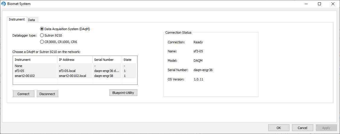
Select Data Acquisition System (DAqM) to display the LI-COR Biomet Data Acquisition Systems that have been configured for the shared SmartFlux 2 or 3 System. Select the Data Acquisition System and click Connect.
Note: The LI-COR Biomet Data Acquisition System must be configured through the Blueprint Utility (software) before it will be listed here.
Connecting a Sutron 9210 or Campbell CR3000, CR1000, or CR6
Sutron 9210
Select Sutron 9210 to displays a list of Sutron 9210 Dataloggers available on the network (same subnet mask as computer). Select a Sutron 9210 from the list or enter an IP address in the Datalogger IP Address field (networked device on different subnet mask as computer) and click Connect.
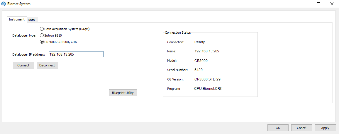
CR3000, CR1000, or CR6
Select CR3000, CR1000, CR6, enter the IP address in the Datalogger IP Address field and click Connect. The datalogger IP address is a user-assigned static IP address that is also set in the datalogger software. When you start logging data, data values from the Campbell Scientific datalogger will be logged and summarized in the SmartFlux System output. See the Campbell Scientific Dataloggers Installation Guide for instructions on programing the CR3000, CR1000, or CR6 datalogger for the SmartFlux System.
Biomet system connection status and data
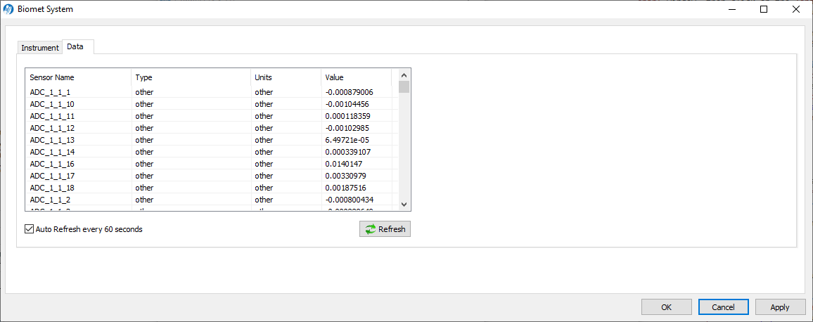
Connection information and recent data are displayed in the window.
- Connection Status: The right side of the Instrument screen displays the datalogger connection status, IP address, model name, serial number, operating system version, and program name.
- Data: After connecting, click the Data tab to display a list of biomet sensors configured for use with the selected datalogger (under Sensor Name). The list displays the Sensor Properties (Type, Units, and Value) for the selected sensor. Note that the Sensors and Sensor Properties are configured through the datalogger software; this list is for reference only.
Connecting an LI-7700
To connect with an LI-7700 Open Path CH4 Analyzer, install an Ethernet cable between the LI-7700 and the network switch. Click the LI-7700 button, or under Site Setup > LI-7700 , click settings ( ) to open the connection window.

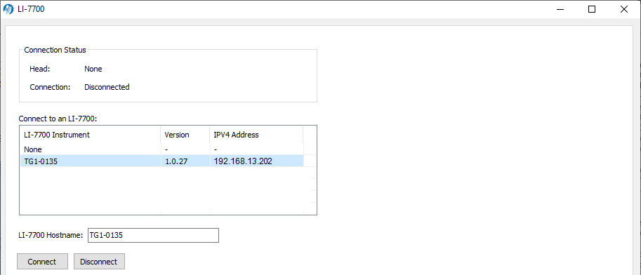
Select the LI-7700 from the list or enter an IP address in the LI-7700 Hostname field (for networked device on different subnet mask as computer) and click Connect. Click Apply or OK.
Important: To synchronize the clocks of the LI-7550 and the LI-7700, be sure to configure the PTP time setting in the LI-7700 to Slave or Automatic.
Connecting to FluxSuite
Any internet-connected LI-COR eddy covariance system that is running the SmartFlux 2 or 3 System can be connected to the FluxSuite Software. FluxSuite provides online results computed by your system in real time, daily email alerts based on thresholds you set, and the ability to assign collaborators to each site. To configure FluxSuite:
- Register for an account.
- Contact LI-COR or your sales representative to register an account.
- Log into your account and create a station key.
- Log into your account.
- Go to the Stations view and click Add Entry.
- Enter a station name and the additional information about the station, then click Save.
- Click the Information button for the station you added, then click Generate Station Key.
- Enter the server information and station key into your gas analyzer.
-

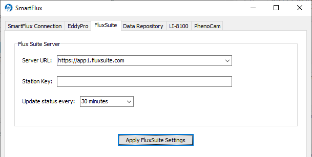
- In the gas analyzer software, click the SmartFlux button.
- Click the tab called FluxSuite.
- Enter the server (www.app1.fluxsuite.com) and station key.
- Check the results online.
- Your system will update the flux results online every 30 minutes.
- Configure your notification settings.
- You can adjust alert thresholds for each variable.
Connecting to a data repository
The Data Repository tab is where you configure the eddy covariance system to push data to a server. You can push raw data (lots of data), complete EddyPro results (a moderate amount of data), or daily summary files (a small amount of data).
The options available include:
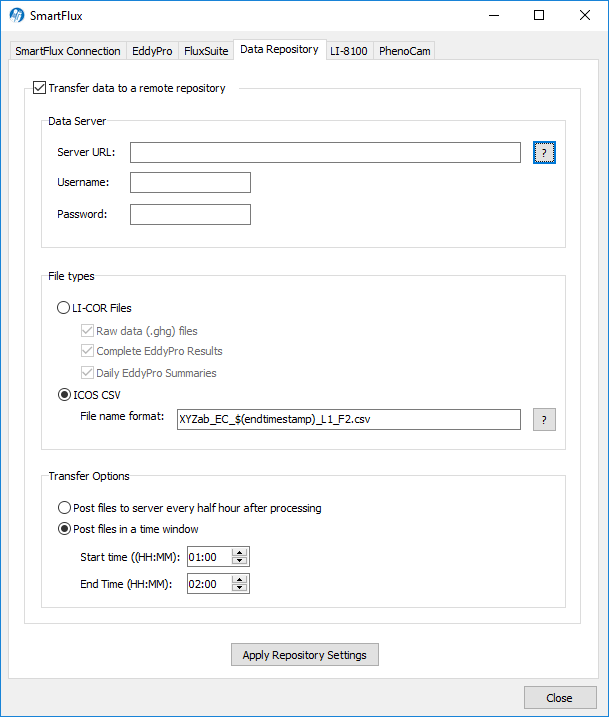
Transfer data to a remote repository: Check this box to enable transfer.
Data Server: Here you enter the Server URL and login credentials. In the Server URL: field, you have some options that enable you to specify which data should be transferred.
Suitable URLs:
- https://server-address
- sftp://server-address/path/$(filename)
- ftp://server-address/path/$(filename)
In the examples above, the server-address is the URL of the server where SmartFlux will transfer data. Depending on how the server is set up, the path may or may not be needed.
SmartFlux expects the server to ask for a username and password, so they are mandatory fields.
Depending on the server implementation, you may want to add other information onto the path of the URL. When any of the items below are added to the URL, SmartFlux will replace the $(variable) with the corresponding value. For example, $(hostname) is replaced with the hostname of the SmartFlux.
| Information | Description |
|---|---|
| $(checksum) | MD5 sum of the file being uploaded |
| $(filename) | The name of the file being uploaded |
| $(fullname) | The name of the file including the path |
| $(hostname) | SmartFlux hostname |
| $(timestamp) | Data collection start time |
| $(endtimestamp) | Data collection end time |
Some examples follow:
- sftp://192.168.100.100/$(filename)
- sftp://192.168.100.100/home/station/$(filename)
- https://some_url.com/upload/etc/$(md5)/$(filename)
File Types: The types of files that are sent to the server can be a combination of the raw data file (.ghg), the full EddyPro output package for each processing period, or a file that contains the daily EddyPro output summaries.
Alternately, if you wish to submit files in the format specified by the ICOS network, choose the ICOS CSV option.
The file name for the ICOS CSV file needs to be specified in the following format:
#[SiteID]_EC_$(endtimestamp)_L#[logger_number]_F#[file_number].csv
- The fields indicated by #[…] must be edited by the user
- The fields indicated by $(variable) are dynamically created by the software
- The text in bold typface must not be modified
For example, for Site ID XYZab, Logger Number 1 and File Number 2, the file name template must be:
XYZab_EC_$(endtimestamp)_L1_F2.csv
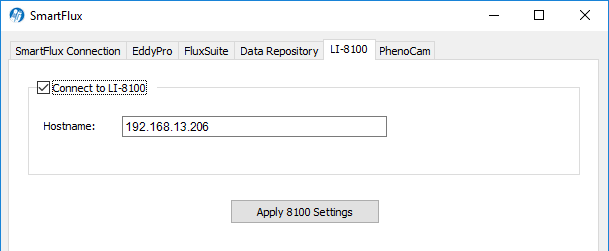
Connecting an LI-8100A system
To connect an LI-8100A to FluxSuite, enter the LI-8100A IP address in the field labeled Hostname. Click Apply 8100 Settings after entering the Hostname.
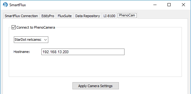
Connecting a PhenoCam camera
Note: The StarDot NetCam SC (PhenoCam) has been replaced by a new model - the NetCamLIVE2. The NetCamLIVE2 is a direct replacement and is supported by SmartFlux 2 and 3 Systems (firmware v2.4.2 and newer).
Under the PhenoCam tab, you can connect to a StarDot PhenoCam or a CC5MPX digital camera. When connected, the images will be posted to FluxSuite (assuming you have registered and configured everything else). To connect with the camera, check the box, then select a camera model. For the StarDot PhenoCam, enter the camera IP address in the field labeled Hostname. For the CC5MPX, enter the Hostname and the MAC Address that is printed on the camera's exterior label. Click Apply Camera Settings to connect the camera to the system.
Configuring the system for cellular communication with the RV50X
If you are using a cellular communication system (Sierra Wireless AirLink RV50X), refer to the LI-COR cellular communication instruction manual for full details. Here, we show how to set the gas analyzer IP address, as required for the cellular communication. We recommend the following IP addresses with the RV50X.
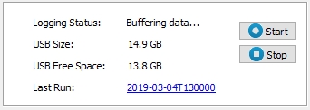
- Stop data logging.
- Click the Stop button on the software dashboard.
- Configure the SmartFlux 3 System for a Static IP Address: Click Settings > Network and enter the IP Address, Subnet Mask, and Default Gateway.
- IP Address: 192.168.13.200, as specified the LI-COR cellular communication instruction manual.
- Subnet Mask: Typically 255.255.255.0
- Default Gateway: Set this to the local IP address of the RV50X (192.168.13.31).
-
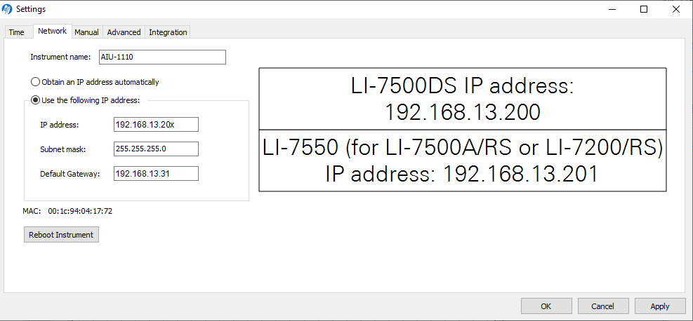
- Reboot the instrument after changing the network settings.
Proceed to configure the RV50X as described in the included documentation.