


Custom event parameter reference
The columns in the Table editor represent the various degrees of freedom that you have to define a custom event. This section describes each.
Code
Code values are how steps are referenced for post event analysis.
Code values do not have to be unique. Rather, all steps that you might wish to include in a common analysis can contain the same code number. For example, the custom version of the induction flash has 11 code 3 steps. Here are the meta and code lines from File structure:
{
"meta": "+tadj 3 +fmax 3 +fk 3 +xl +dspk",
"code": "2 3 3 3 3 3 3 3 3 3 3 3 7",
}
Those 11 steps serve to smoothly adjust duration and output rates to provide high density output at the start of the flash, tapering off to less frequent output later on in the flash. The meta codes calling for finding the max value (+fmax 3) and the fast kinetic analysis (+fk 3) reference step 3, so all steps labeled 3 get included in those analyses. You could label them differently if you wish, but the meta codes would then have to reference a lot of code values, leaving you something like this
{
"meta": "+tadj 3 +fmax 3,4,5,6,7,8,9,10,11,12,13 +fk 3,4,5,6,7,8,9,10,11,12,13 +xl +dspk",
"code": "2 3 4 5 6 7 8 9 10 11 12 13 17",
}
A step's Code value should be an integer between (and including) 2 and 53. The code values below 16 have always been used in standard flashes (RECT, MPF, INDUCTION, and DARKPULSE). Historically, the code value was used to trigger certain computations by the fluorometer itself. For example, if there were any steps with code 3, that would trigger an FMAX computation using all code 3 records. With custom event firmware, however, computations are only triggered via meta commands (see Meta commands), not code numbers.
Therefore, code numbers can be anything you want, between 2 and 53. They do need to be "in sync" with the meta commands, however.
Modrate
There are dependencies among modrate, outrate and duration. It all starts with modulation rate, which determines the basic time period (1/modrate) in which measurements and actions during the flash event occur. For a saturating flash, one normally uses the highest modulation rate (250 kHz), yielding a 4 µs event cycle period in which the fluorometer operates. See Figure 8‑97 for a detailed illustration.
Outrate
The outrate for a step, the frequency with which fluorometer outputs data, cannot exceed the modrate. Usually one uses a much lower outrate, providing averaging and a manageable data flow. However, outrate needs to divide evenly into modrate. Table 8‑15 shows the available outrate values for a few of the available modrate values.
Example: If modrate = 250000 Hz, the table indicates (by "ok") that 25000 Hz is an acceptable outrate (250000/25000 is an integer), but not 20000 Hz (250000/20000 is not an integer).
| outrate | period | modrate (Hz) | |||||||
|---|---|---|---|---|---|---|---|---|---|
| (Hz) | (µs) | 2000 | 1000 | 500 | 200 | 100 | 50 | 20 | 10 |
| 2000 | 500 | ok | — | — | — | — | — | — | — |
| 1000 | 1000 | ok | ok | — | — | — | — | — | — |
| 500 | 2000 | ok | ok | ok | — | — | — | — | — |
| 400 | 2500 | ok | — | — | — | — | — | — | — |
| 250 | 4000 | ok | ok | ok | — | — | — | — | — |
| 200 | 5000 | ok | ok | — | ok | — | — | — | — |
| 125 | 8000 | ok | ok | ok | — | — | — | — | — |
| 100 | 10000 | ok | ok | ok | ok | ok | — | — | — |
| 80 | 12500 | ok | — | — | — | — | — | — | — |
| 50 | 20000 | ok | ok | ok | ok | ok | ok | — | — |
| 40 | 25000 | ok | ok | — | ok | — | — | — | — |
| 25 | 40000 | ok | ok | ok | ok | ok | ok | — | — |
| 20 | 50000 | ok | ok | ok | ok | ok | — | ok | — |
| 16 | 62500 | ok | — | — | — | — | — | — | — |
| 10 | 100000 | ok | ok | ok | ok | ok | ok | ok | ok |
| 8 | 125000 | ok | ok | — | ok | — | — | — | — |
| 5 | 200000 | ok | ok | ok | ok | ok | ok | ok | ok |
| 4 | 250000 | ok | ok | ok | ok | ok | — | ok | — |
| 2 | 500000 | ok | ok | ok | ok | ok | ok | ok | ok |
Duration
The duration of a step is simply how long you wish the step to last, in µs. This is fairly simple, but there is a subtlety here, especially for short durations: the actual time a step lasts will always be an even multiple of the output period.
Suppose modrate = 250000 Hz and outrate = 25000 Hz. duration should then be an integer multiple of the output period, 40 (1 / 25000 = 40, or look it up in Table 8‑15). Suppose we specified a duration of 500 µs (500 / 40 = 12.5), which isn't allowed. What happens? When that step executes, even though you asked for 500 µs, it will actually last 520 µs, which is an integer (13) multiple of 40.
Qr
The Qr value determines the red actinic for the step. This is typically the primary item being changed for a flash. Square flash corrections and ramping can be done on this value, but those are controlled by the next item, Qr_delta.
Qr_delta
The Qr_delta element provides capabilities for ramping the red actinic during one step of a custom flash. For example, specifying a value of 100 will cause Qr to increase linearly during that step by 100 µmol m-2 s-1. A value of −1000 would cause it to decrease linearly by 1000 µmol m-2 s-1.
To specify a percent ramp (down) in the same way that an MPF phase 2 is done, use r followed (no space!) by an integer value that represents the percent ramp (e.g., r25). The fluorometer will compute the appropriate value of Qr_delta as

where R is a percent ramp [0...100], and Qr0 is the value of red actinic prior to the flash.
The r code is useful when defining a flash step, because you might not know what Qr0 will be at the time of the flash’s execution.
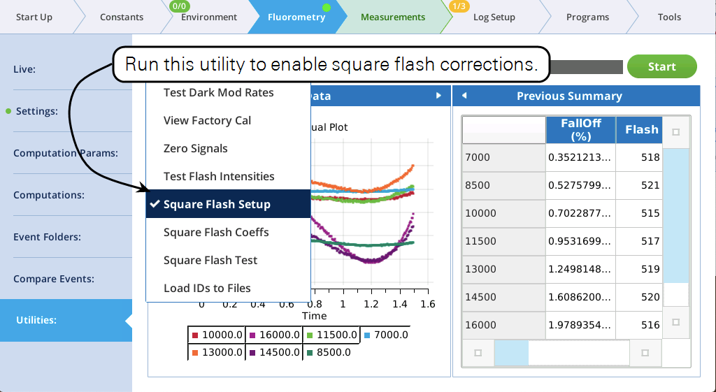
Specifying a Qr_delta of s instead of a value will call for a square flash correction to be applied to that step. A square flash correction can be enabled for a maximum of 4 steps.
Also, square flash corrections count against the 38 total step limit. One square flash correction can add as many as 12 "hidden" steps, depending on that step's Duration. A square flash correction of a 1 second step uses 12 extra steps, but fewer if the step is less than 1 second. Table 8‑17 relates step duration (in ms) to the "cost" in steps of doing a square flash correction. For example, applying a square flash corrected to a step of 400 ms will reduce the total available steps by 7.
| Duration (ms) | Steps |
|---|---|
| ≤ 1,000+ | 12 |
| ≤861 | 11 |
| ≤733 | 10 |
| ≤615 | 9 |
| ≤506 | 8 |
| ≤408 | 7 |
| ≤320 | 6 |
| ≤241 | 5 |
| ≤173 | 4 |
| ≤115 | 3 |
| ≤67 | 2 |
| ≤28 | 1 |
Hint: Don't "waste" a square flash correction on any step shorter than about 10 ms. Also, the correction is only applied if a square flash calibration has been done, and if the correction is enabled at the time of the flash.
Qb
Qb is the value of the blue actinic LEDs during a step. To leave these unchanged, simply specify a value of x.
Qd
Qd is the value of the far red LEDs during a step. To leave these unchanged, simply specify a value of x.
Qm_pk
Qm_peak is the value of the peak modulation for the red measuring LEDs. Since computations involving modulated fluorescence values in and out of an event need to be made using the same Qm_peak setting, this should normally always have a setting of x (no change).