Introduction to the LI-710 and Water Node
The LI-710 Evapotranspiration Sensor measures the total transport of water from evaporation and transpiration over an area. The output from the LI-710 is evapotranspiration, energy flux, and other parameters in 30-minute increments. The LI-710, when paired with an IoE Module, is a Water Node on LI-COR Cloud.
If you have just received your LI-710, check the packing list to be sure you have everything that you ordered. The LI-710 may include some or all of the following components.
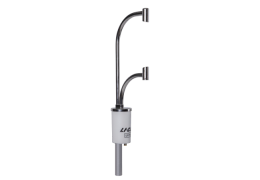
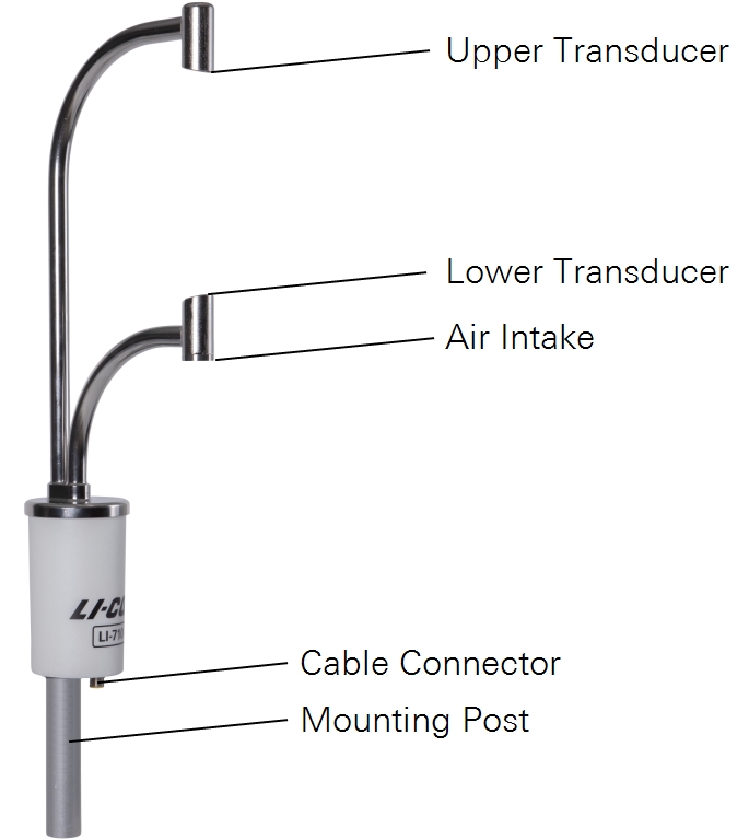
LI-710 Evapotranspiration Sensor
Part number 9971-010
The sensor features one cable connector for power and data and one mounting post for mounting on an IoE Module or tripod using a 1" (2.54 cm) fitting.
Data and power cable
Part number 392-19605
Each sensor includes a 5-meter long combined data and power cable. The cable connects to the SDI-12 terminals on a datalogger.
Spares kit
Part number 9971-008
Each LI-710 is shipped with a spares kit, which includes replacement parts and a tool for the instrument. See Table 1‑1 for a complete list.
Filter pack
Part number 9971-015
Five replacement filters are included in the spares kit. Additional filter packs are available for purchase. The filter pack includes five filters and five O-rings.
Replacement pump
Part number 9971-016
One replacement pump is included in the spares kit. Additional pumps are available for purchase. The kit includes a pump, two O-rings, and four screws.
Stevens HydraProbe
Part number 900-19016
The IoE Module supports the Stevens HydraProbe (firmware v4 and up) for soil moisture, temperature, and electrical conductivity measurements.
IoE Module
The IoE Module may include some or all of the following components and services:
- Cellular service plan and access to LI-COR Cloud (extendable).
- Backup data logging to a removable Micro SD card (all configurations).
- Built-in charge controller for the solar power supply (all configurations).
- Solar and battery power supply (optional).
- Mounting structure and enclosure for sensors and equipment (optional).
The IoE Module powers sensors for continuous long-term operation, while simultaneously posting data to the LI-COR Cloud via a cellular network. It allows operators to view data and assess results from sensors remotely.
IoE configurations are given in Table 1‑2 and described in the following sections.
| Part # | LI-COR Cloud | IoE Module | Frame and Mast | Solar Power |
|---|---|---|---|---|
| 99512-014 | - | Yes | - | - |
| 9000-01 | Yes | - | - | - |
| 9000-02 | Yes | Yes | Yes | Yes |
| 9000-031 | Yes | Yes | - | - |
| 9000-04 | Yes | Yes | Yes | - |
IoE module only
Part number 9000-03
The stand-alone IoE module includes the enclosure, electronics, power and data cable for the sensor (392-20750), cellular service, and LI-COR Cloud data service. Cellular and LI-COR Cloud service contracts can be extended. We recommend the optional hardware mounting kit (9000-05) with this configuration.
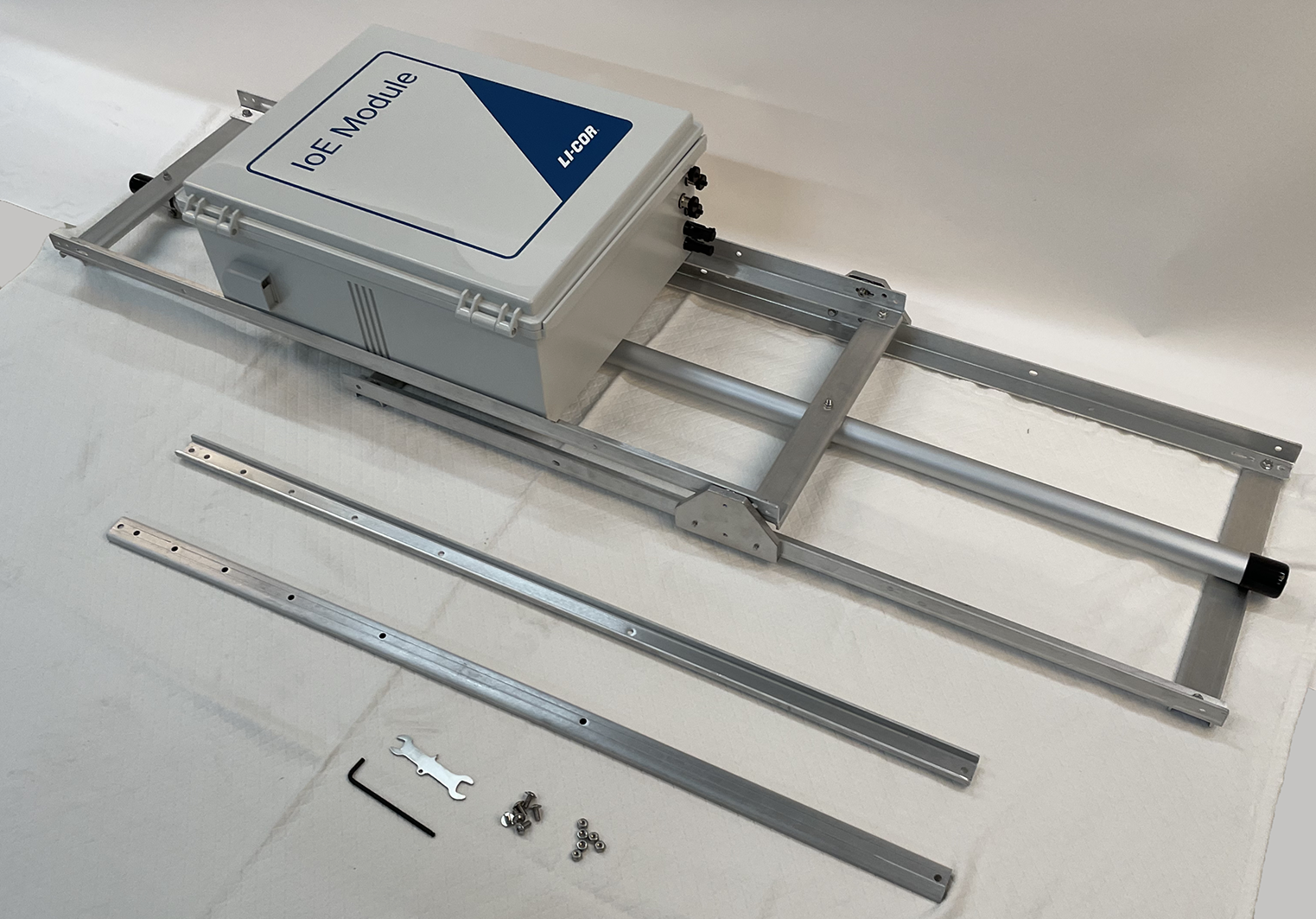
IoE module, mast, and frame assembly
Part number 9000-04
This configuration includes everything listed previously, plus the frame with mast, assembly hardware, instrument and guy wire adapter, earth anchor kit, grounding kit, and tool kit. The mast allows height adjustment resolution of 20 cm at heights from 2 to 5 meters.
Assembly hardware kit
The hardware kit includes parts and accessories to assemble the system.
| Description | Part # |
|---|---|
| Braces; 1.25×0.5" U-channel; 39" long | 98512-052 |
| M6×1 6-mm stainless lock nuts (4) | 157-20957 |
| M6×1 12-mm cap screws (4) | 151-20958 |
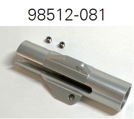
| Instrument and guy wire adapter (1) | 98512-081 |
| Instrument and guy wire adapter (discontinued) | 98512-013 |
| M8×1.25 set pins (2) | 155-16763 |
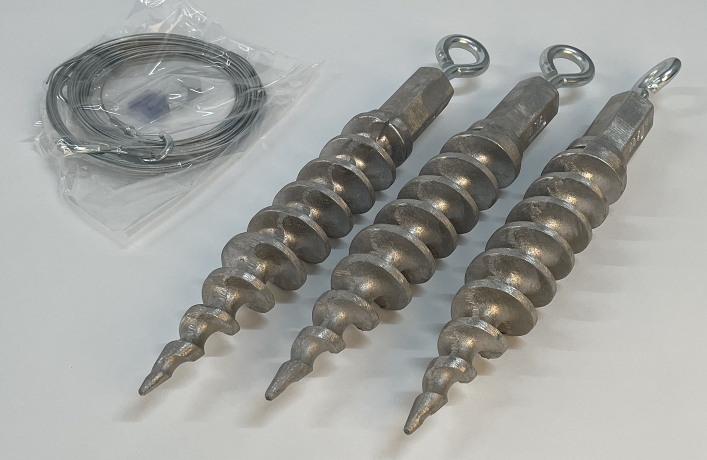
Earth anchor kit
The anchoring kit includes hardware to stabilize the mast when it is extended.
| Description | Part # |
|---|---|
| 14-inch earth anchors with eye-bolts (3) | 609-20822 |
| Guy wires with clip (3) | 609-20846 |
| Gripple cable locks (3) | - |
| Gripple release key (1) | 611-21003 |
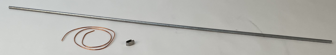
Grounding kit
The grounding kit includes hardware for an earth-ground.
| Description | Part # |
|---|---|
| Ground rod (1); 1.5 meter | 609-20976 |
| Ground wire (1); 2 meters; 8-gauge | 374-12937 |
| Ground rod clasp (1) | 354-20819 |
Tools
Several assembly tools are included.
| Description | Part # |
|---|---|
| 10 mm and 1/2" wrench (1) | 98512-066 |
| Multipurpose screwdriver (1) | 611-07902 |
| 4 mm hex key (1) | 611-21236 |
IoE module, mast, frame, battery, and solar panel
Part number 9000-02
The turnkey IoE Module includes everything listed previously, plus a solar panel, battery, and hardware for the solar power and battery. The panel rails provide angle adjustments to allow the solar panel to face the sun in different latitudes and seasons.
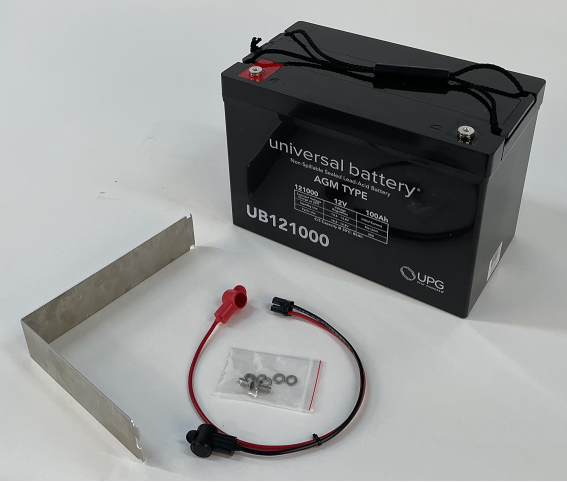
Battery kit
Part number 99512-031
The battery kit includes a 100-Ah 12-volt absorbed glass mat (AGM) battery, cables, and a bracket to secure the battery.
| Description | Part # |
|---|---|
| 100-Ah 12-volt AGM lead-acid battery | 442-20708 |
| Battery cable assembly | 99512-022 |
| Battery hold-down bracket | 98512-065 |
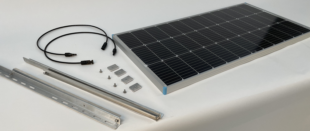
Solar panel kit
The solar power kit includes a solar panel and hardware for the power supply.
| Description | Part # |
|---|---|
| 100-watt 12-volt solar panel | 590-20735 |
| Solar panel extension cables | 392-20841 |
| Solar panel bracket assemblies (2) | |
| Angle bracket (installed) | 98512-050 |
| U-channel bracket (installed) | 98512-051 |
| 16-mm serrated flange bolts (installed) | 150-20955 |
| M6×1 6-mm nylon lock nuts (installed) | 157-20957 |
| 1/4" clevis pin with 1/16" cotter pin | 186-20847 |
| M6×1 12-mm cap screws (4) | 151-20958 |
| Panel clamps (4) | 98512-010 |
Sensor cable
Part number 392-20750
Each IoE Module includes a sensor cable to connect the LI-710 or LI-720 to the SENSOR connector on the IoE Module. It is a 5-meter long 5-pin cable with connectors on each end.
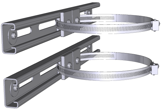
Optional mounting hardware
Part number 9000-05
Stand-alone IoE modules (9000-03) can be mounted with the mounting hardware kit, which is compatible with a vertical mast, horizontal cross arm, or pipe at nearly any angle. The kit includes two brackets, two band clamps, and additional hardware.
Warning: Do not use the optional mounting hardware with the battery kit (99512-031) or any other heavy battery. The mounting hardware (9000-05) is not strong enough to safely hold the battery, and may present a risk of injury if a battery is installed.
Optional auxiliary power cables
Power cables are used to power the IoE Module from external power (9 to 33 VDC, 3.0 A). Power cables are available in three lengths:
| Description | Part # |
|---|---|
| 3-meter power cable | 8150-706 |
| 5-meter power cable | 9975-030 |
| 25-meter power cable | 9975-056 |
Enclosure and electronics
The enclosure houses the electronics, antennas, and other components.
Warning: Read and understand the operating instructions and safety information before using this equipment. Failure to understand the safety information may result in bodily injury, damage to equipment, or unsatisfactory results.
Components
Components of the enclosure are labeled and described below.
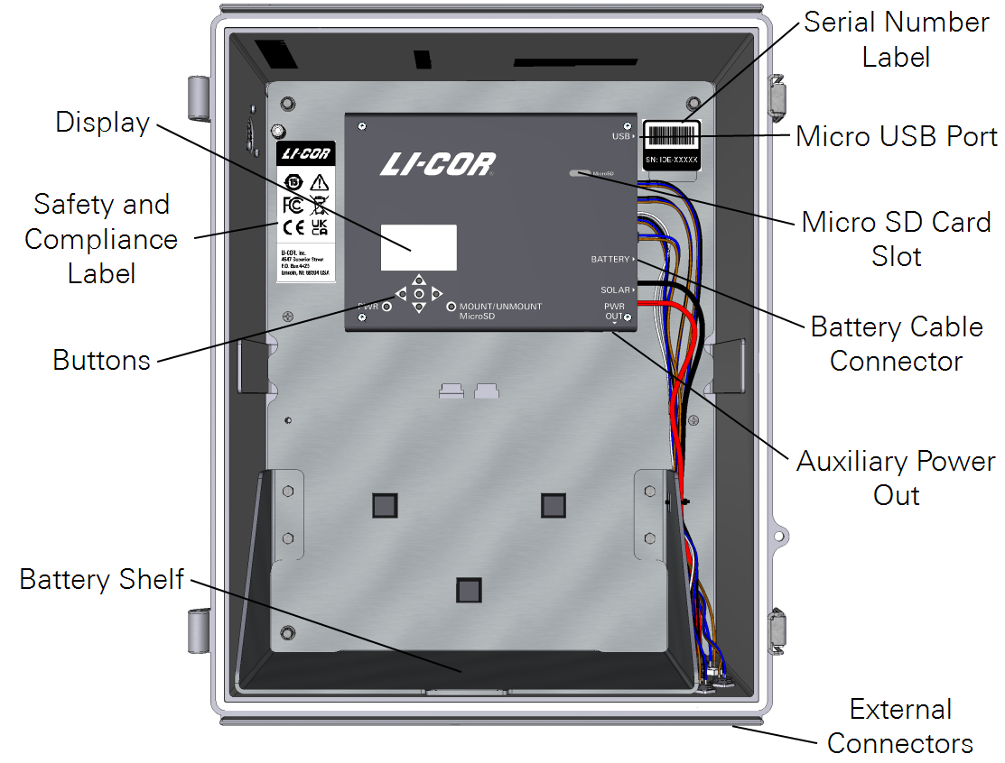
- Display: Monochrome display that presents status and configuration information. See IoE module interface reference for a tour.
- Buttons: Buttons include power (
 ), navigation (
 ,
,  ,
,  ,
,  ), select (
 ), and mount/unmount card.
 - Battery Shelf: To support the optional battery. Always use the hold-down bracket when a battery is installed.
- Serial Number Label: The serial number label gives the product serial number, which may be useful if you need technical support.
- Micro USB Port: To connect to a computer for manual firmware updates. Accepts a Micro-B connector.
- Micro SD Card Slot: The slot is for the included Micro SD card to store a backup of data. An 8 GB card is included (part number 616-21301). The 8 GB card can store many years of data, typically. Most micro SD cards (FAT12, FAT16, FAT32, and ExFAT format) will work as long there is free space for files.
- Battery Cable Connector: The cable from the optional 12-volt lead-acid battery attaches to this connector.
- Auxiliary Power Out: One auxiliary power supply is provided inside the enclosure. Contact LI-COR technical support if you want to use the power out.
External connectors
The external connectors are for sensors, auxiliary power, and solar panels.
Warning: Read and understand the operating instructions and safety information before using this equipment. Failure to understand the safety information may result in bodily injury, damage to equipment, or unsatisfactory results.
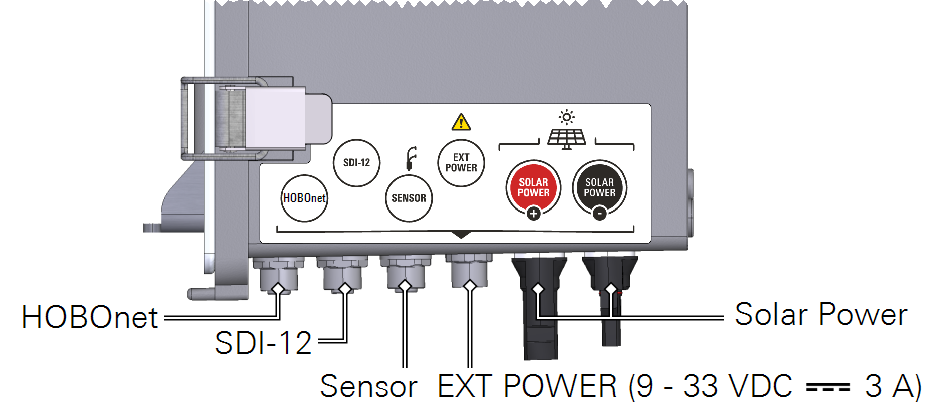
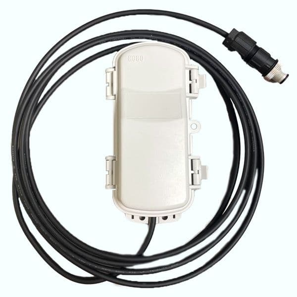
- HOBOnet Connector: For the HOBO Node Link (available on new IoE Modules).
- SDI-12 Connectors: One connector for SDI-12 devices. Power, configuration, and data transfer are supported. The device must have a 5-pin sealed connector. The Stevens Soil Probe available from LI-COR (part number 900-19016) has the connector. The SDI-12 power supply provides 12 VDC with a maximum of 2.5 amps total, including the Sensor Connector.
- Sensor Connector: Accepts the LI-710 or LI-720 cable (392-20750). It features a 5-pin sealed connector for a combined SDI-12/RS-232 port. The SDI-12 power supply provides 12 VDC with a maximum of 2.5 amps total, including the two SDI-12 connectors.
- Auxiliary Power Input: For operation from an external power supply (other than the solar panel or battery). Supports 9 to 33 VDC, 3.0 A maximum current. Be sure the power supply is stable. Unstable power may result in damage if power is lost while data are being written.
- Solar Panel Inputs: To attach the solar panel extension cables. The maximum input is 9.15 A (circuitry is current limited to prevent damage). Compatible panels should output 17 to 21 V, with a maximum open circuit voltage of 32 V.
Extension cable (optional)
Part number 392-20529
25-meter extension cable with weather-resistant connectors on each end. Extends the IoE Module data/power cable for a total length of 30 meters.
Warning: Do not connect solar panels with voltage rating that is higher than specified. Doing so can damage equipment or cause injury.
HOBOnet Water Node Network
The optional Water Node Network provides supplemental data to the water node. All sensors send data to the Node Link, which is connected to the IoE Module. Measurements from a Node Link are available on LI-COR Cloud as part of the Water Node. The Node Link is supported by new IoE Modules (indicated by the HOBOnet label and cable connector) with firmware v1.2 or newer.
Node Link
Part numbers 900-21996 (NA), 900-21995 (EU), 900-21997 (AU)
The Node Link communicates with wireless sensors and the IoE Module. It connects to the IoE Module with a 9-pin threaded connector. A Node Link allows up to 50 sensor nodes to be added to a IoE Module. Node Link data are uploaded to LI-COR Cloud.
Each Water Node Network includes the sensors given below. Duplicates and other sensors can be added as well.
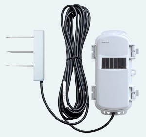
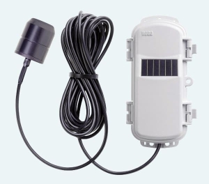
Soil moisture, temperature, and electrical conductivity sensor
Part number RXW-T12-xxx
Measures soil water content and conductivity. Each node network package includes three soil sensors.
Air temperature and relative humidity sensor
Part number RXW-THC-xxx
Measures ambient air temperature and humidity. One sensor is included.
Rain gauge
Part number RXW-RGF-xxx
Measure liquid precipitation and rainfall intensity. One sensor is included.
Solar radiation meter
Part number RXW-LIB-xxx
Measures total solar radiation. One sensor is included.
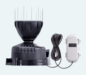
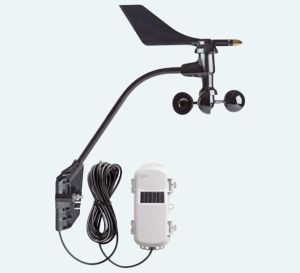
Wind speed and direction sensor
Part number RXW-WCF-xxx
A cup and vane anemometer measures wind speed and direction. One is included.
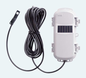
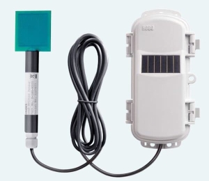
Leaf wetness sensor
Part number RXW-LWA-xxx
Measures leaf wetness. One sensor is included.
Summary of theory of operation
The LI-710 uses eddy covariance calculations that are optimized for the hardware and sensor configuration. It combines vertical wind speed measurements with high-precision relative humidity measurements to compute evapotranspiration from the area surrounding the sensor. When the prevailing wind directions around the LI-710 are random or uniform, measurements represent the surrounding area and vegetation (known as the “fetch footprint”). When wind is from a prevailing direction, measurements represent the land area and vegetation under the prevailing winds. The fetch footprint encompasses an area around the LI-710 that is 50 to 100 times the height of the sensor (e.g., a 2-meter height above the canopy has a fetch footprint of 100 to 200 meters).
The LI-710 does not provide horizontal wind information and therefore, it does not report the fetch footprint of the measurement. In a proper deployment, the footprint will encompass a uniform land area surrounding the sensor or an area upwind of the prevailing wind direction (see Installing the LI-710 for more information).