Maintenance
Some routine attention will ensure that the LI-720 and IoE Module provide dependable performance over long time periods, and will help you get more complete, continuous datasets.
Updating firmware
LI-720 firmware
After updating the LI-720 firmware, be sure to re-add the LI-720 to the IoE Module to acquire the latest LI-720 configuration file from LI-COR Cloud (see Reinitialize after firmware updates).
Note: Download the latest version of the CarbonWare application before going to the site if your computer is unable to connect to the internet at the field site. The latest LI-720 firmware is included with the CarbonWare app.
Firmware updates are carried out with the USB adapter cable (part number 99512-062). To update the firmware:
-
Download the CarbonWare app to your computer.
Firmware is included with the CarbonWare application here.
-
Connect the USB adapter cable between the LI-720 and computer.
Do not use a USB extension or device extension cable when powering the LI-720 from a 5 V USB power supply. Extension cables may result in voltage drops that affect both power and digital communication. Do not deploy the LI-720 while powered from 5 V USB power. The LI-720 requires 9 to 33 VDC for field operation.

-
In CarbonWare, connect with the LI-720 and click the LI-720 Firmware tab.
The firmware running on the LI-720 and the latest version are both displayed. If an update is needed, click Update LI-720 to apply it.
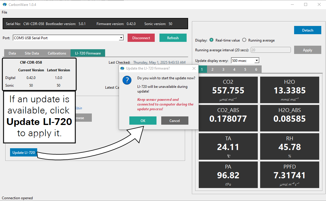
-
Keep the sensor powered and connected to the computer during the update.
Reinitialize after firmware updates
If you have updated the LI-720 firmware, be sure to apply the latest device configuration on the IoE Module. This is accomplished by deleting the LI-720 and adding it again, which ensures that the IoE Module has acquired the compatible configuration file from LI-COR Cloud. Follow these steps:
-
Enter the Device Setup screen and select device to remove.
-
Long-press the Select button (
 ) until prompted:
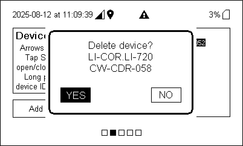
-
Highlight YES and then press Select (
). -
Save the configuration.
Press Right (
 ) once to open the prompt, then press Select () to save the changes. You MUST save changes for the settings to be applied.
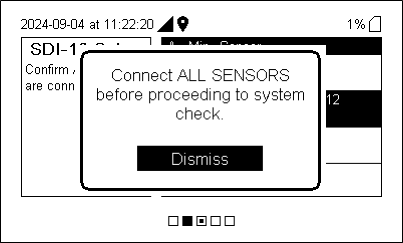
-
Follow the steps in Initial setup to reconfigure the sensor.
IoE Module firmware
If updating the IoE Module from firmware 1.0 or 1.1, be sure to have all SDI-12 devices connected during the update. If they are not connected, configuration data will be lost and you will have to re-add the sensors. The update requires cloud connectivity.
IoE Module firmware updates are loaded from a computer to the IoE Module using the USB port. To apply the update:
-
Download the file to your computer.
Firmware files are available from Firmware Downloads. The file name is
cwcfw_1.2.0.ioe_pkgor something similar. -
Power off the IoE Module.
Press the power button (
 ) and then select Yes to power off the device.
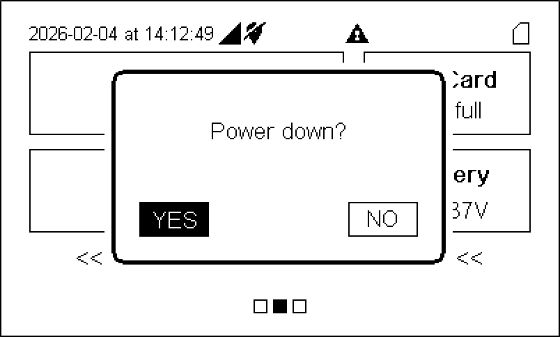
-
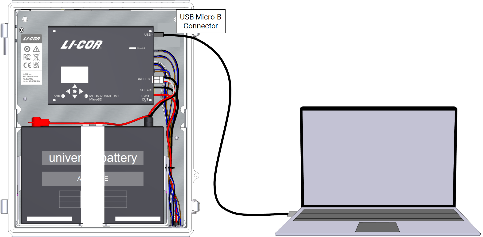
Connect a USB cable between the module and your computer.
The USB connector is labeled in the IoE Module. It accepts a USB Micro-B connector.
Caution: The Micro-B connector is fragile. Do not apply lateral force to the cable connector when inserting and removing the cable to avoid damaging the circuit board.
-
Power on the IoE Module.
It will start in update mode and appear as a USB drive on your computer called LI-COR_IOE.

-
Drag the file or copy and paste the file to the folder.
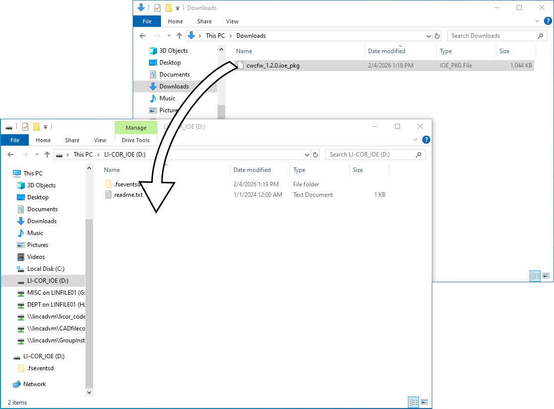
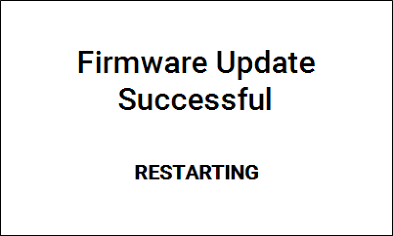
The IoE Module will apply the update. Progress is shown on the display.

-
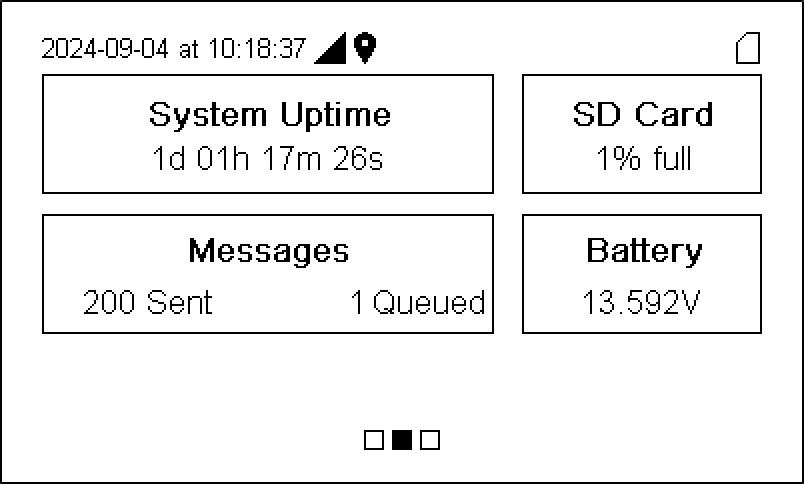
Watch as the IoE Module restarts.
The initialization screen displays the firmware version briefly before advancing to the home screen.

-
Disconnect the USB cable.
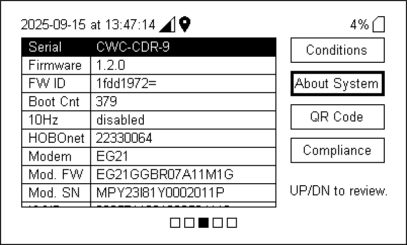
To check the version number, press left once ( ) and down once (
 ) to view About System, where the firmware version is displayed.
LI-720 Maintenance
Basic sensor checkup
You can conduct a basic check just by inspecting the LI-720. Look for the following:
- Inspect the vertical sonic transducers to be sure they are not covered in dirt, bird droppings, or other deposits. Clean them with a soft, damp cloth. Use a mild detergent if needed.
- Inspect the optics for dirt, bird droppings, or other deposits. Check the RSSI (see Checking and adjusting the signal strength). If the optics are dirty or the RSSI is low, clean the lenses with water and a soft, lint-free cloth. Use a mild detergent if needed.
- Inspect the horizontal sonic anemometer components. Look for insect colonies or other foreign objects. Clear anything that might obstruct the airflow or ultrasonic signals.
- Inspect the radiation shield that covers the air temperature and RH sensor. Clear any obstructions.
- Wipe the quantum sensor with a soft lint-free cloth. Use mild detergent if needed. Do not use alcohols on the quantum sensor; alcohols can damage the diffuser.
Calibrations
User calibrations adjust the output from the sensor to ensure accurate measurements. Check the calibration in a controlled environment such as a lab or office. Do not attempt to calibrate while installed on a tower or tripod.
Before adjusting the zero and span, check the RSSI and clean the optics (see Checking and adjusting the signal strength). Wipe each lens with a soft lint-free cloth. Use mild dish soap and water to remove any stubborn deposits from the lenses. Wipe the lenses dry after cleaning.
Calibration gases
A user calibration is only as good as the gas. For the zero gas, use a tank of CO2-free dry air or a user-supplied pump and chemicals such as soda lime and magnesium perchlorate or Drierite® to scrub CO2 and H2O from the air. For the CO2 span, use a tank with a known CO2 concentration that is above the typical concentrations you will measure. For most applications, 450 to 500 ppm CO2 balanced in air is good enough. For the H2O span, use a dewpoint generator such as the LI-610 or Sable Systems DG-4 to create an air stream with a known, stable dewpoint.
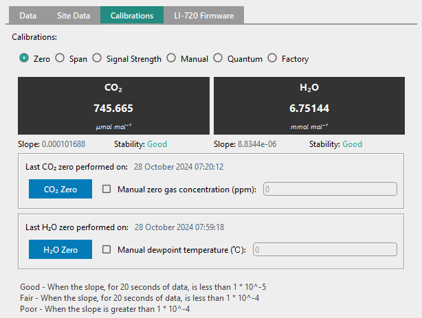
Setting the H2O and CO2 zeros
Start with the zeros. A zero adjustment changes every measurement by a fixed amount.
-
Clean the lenses with a soft, lint-free cloth.
Use a mild detergent, if needed. Dry the lenses. Check the RSSI. If it is less than 95, clean the optics again.
-
Insert the calibration fixture into the optical path, being cautious to not apply pressure to the upper and lower spheres - do not deform the structure.
The hose barb on the calibration fixture is the inlet; install the fixture so the inlet is next to the bottom sphere. Loosen the set screw and insert the shroud into the optical path. Extend it so that each end surrounds the lens and is in gentle contact with the sphere. Tighten the set screw. The calibration fixture will not seal. It should have outward leaks from the top, bottom, and the vent hole.
-
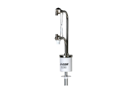
Connect a zero gas to the hosebarb on the calibration fixture.
The zero gas can be from a tank (Figure 8‑1) or created with scrubbers and a user-supplied pump (Figure 8‑2).

Figure 8‑1. Calibration gas can be from a tank. 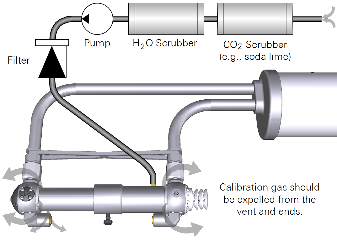
Figure 8‑2. Zero gas can be created with scrub chemicals, a pump, and filter. -
Set the flow rate to approximately 1 liter per minute.
Allow the gas to flow through the cell while observing the readings in the CarbonWare application. The application reports the slope and provides guidance about the stability for a zero or span using a 20-second running average.
- Poor: Slope >1×10⁻⁴ (20 second running average).
- Fair: Slope <1×10⁻⁴
- Good: Slope <1×10⁻⁵
-
When the interface reports that the reading is Good (allow up to 20 minutes), click Zero for each gas.
-
Verify that the readings have changed to match the zero gases.
Setting the CO2 span
-
Connect a tank of high-quality span gas that has a known CO2 concentration.
-
Set the flow rate to about 1 liter per minute.
-
Allow the gas to flow through the cell while observing the readings in the CarbonWare application.
-
Enter the concentration of the span gas.
-
When the interface reports that the stability is Good, click CO2 Span.
-
Verify that the reading has changed to match the span gas.
Setting the H2O span
-
Connect an air stream with a known dew point.
-
Set the flow rate to about 1 liter per minute.
-
Allow the air to flow through the cell while observing the readings in the CarbonWare application.
-
Enter the Dewpoint Temperature (°C) of the air stream.
-
When the stability indicator shows Good, click H2O Span.
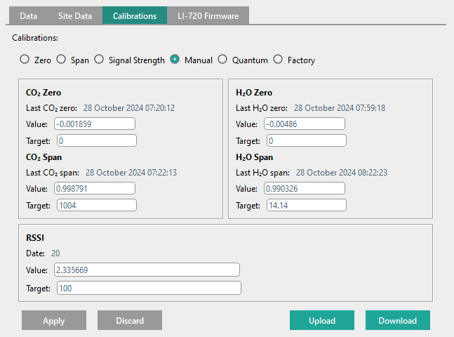
Under the Manual page, verify that all intended calibrations have a new value and updated date.
Checking and adjusting the signal strength
Signal strength (RSSI for Residual Signal Strength Indicator) indicates the relative strength of optical system. RSSI decreases when the optics are dirty. You can adjust the RSSI scale so it has a maximum near 100 to simplify interpretation of the measurement. When RSSI is scaled to a maximum of 100, clean optics are indicated by an RSSI >95.
-
Clean the optics.
It is undesirable to rescale the RSSI while the optics are dirty. If low, clean the optics with mild detergent and a soft, lint-free cloth.
-
When the lenses are clean, check the RSSI in the CarbonWare app.
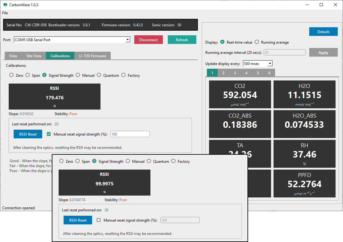
-
To rescale RSSI, enter a maximum and click Reset.
For simplicity, RSSI should have a maximum near 100.
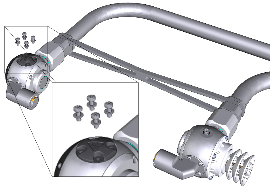
Replacing desiccant and scrub chemicals
A small packet of desiccant and CO2 scrub chemical is in each of the upper and lower gas analyzer housings. The packets keep the housing interior free of water vapor and CO2 gas. We recommend replacing them if the RH in the lower housing is >4%, as indicated in the variable RH_src (if using CarbonWare, see Adding variables to the display list). At an RH_src >4% for 10% of samples in a 30-minute reporting period, the LI-720 will report an issue in the diagnostics for that 30-minute flux result (see Table 7‑1).
-
Both the upper and lower housings have scrub packs. Always replace both of them at the same time.

-
Do not open the packs until you are ready to install them. Install the replacement scrub packs promptly after receiving them.
-
Complete the procedure in dry ambient air, such as a room or vehicle cab with the air conditioning on. The scrub packs may become depleted if exposed to humid air prior to installation.
| Part Number | Description |
|---|---|
| 99512-080 | Scrub Pack Kit |
| 99512-058 | Scrubber Assembly (2) |
| 98512-092 | Custom Washer (2) |
| 150-14386 | Machine Screw; M2 x 6 mm (12) |
Warning: Scrub packs enclose small quantities of Ascarite™ II and magnesium perchlorate. These chemicals may be hazardous. Wear goggles and skin protection (e.g., latex gloves). Do not breath dust or allow the chemicals to come into contact with your skin. Check local regulations before discarding the scrub packs. For SDS, go to licor.com/support and search for SDS.
To replace the scrub packs:
-
Power off the sensor, remove it from the tower, and set it on a workbench.
Handle the instrument carefully and avoid impacts.
-
Remove the four screws (PH1 Phillips driver) and washers that secure upper the scrub pack.
The old screws and washers can be discarded. Be sure to dispose of the packs safely and in accordance with local laws.
-
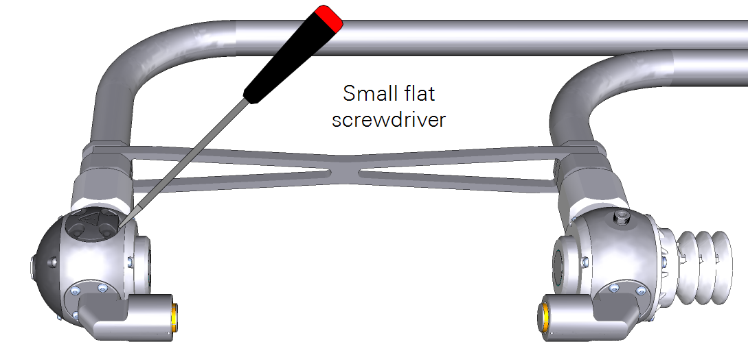
Pull the scrub pack straight up.
Use a small flat screwdriver to dislodge it, and be sure the O-ring comes out with the scrub pack.
-
Open the new scrub pack only when you are ready to install it.
Do not open scrub packs early, as doing so will reduce the scrubbing efficacy. Install them immediately after opening the package.
-
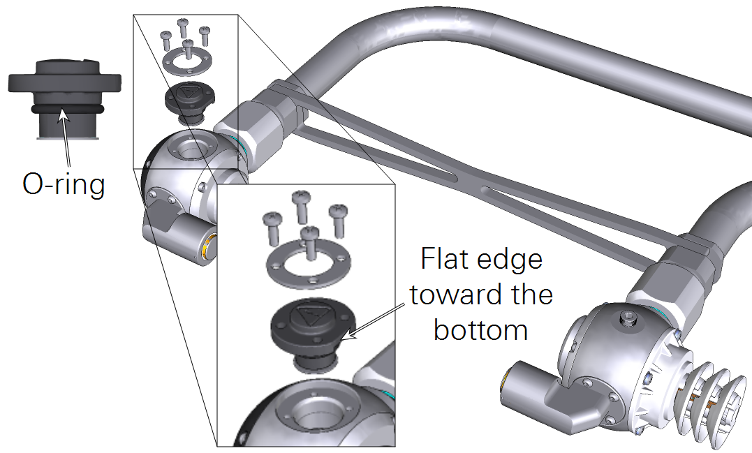
Be sure the O-ring is in place, and then press the new scrub pack into place.
The flat side should be toward the bottom of the sensor.
-
Insert each screw into the ring washer and tighten until hand-tight.
The kit includes four extra screws.
-
Repeat this with the scrub pack in the lower housing.
After replacement, it will take some time to scrub the volumes of CO2 and water vapor. At an RH_src >4% for 10% of samples in a 30-minute reporting period, the LI-720 will report an issue in the diagnostics for that 30-minute flux result. Allow at least 24 hours for the scrub packs to remove CO2 and moisture from the housings. Diagnostics related to RH_src should clear after several hours or days.
Replacing the air temperature and RH sensor
The external temperature and RH sensor is protected by the solar radiation shield. If the readings are implausible or -9999, replace the sensor. One spare is included with the spares kit (part number 99512-007). Additional sensors are available for purchase.
To replace the temperature and RH sensor:
-
Power off the sensor, remove it from the tower and set it on a workbench.
-
Remove the four screws (PH1 Phillips) and washers that secure the radiation shield.
-
Remove the radiation shield and collect the O-ring.
-
Grip the sensor and pull it free from the connector.
-
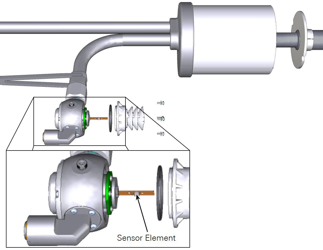
Insert the new sensor.
Handle it carefully. Avoid bending the component. Grip it by the end. Do not touch the element with bare fingers. The sensor element faces the front.
-
Be sure the O-ring is on the white radiation shield, and align the slit in the foam pad with the sensor and gently maneuver the radiation shield into position.
-
Tighten the screws to snug.
-
Power on the LI-720 and check the temperature and RH values.
If the readings are plausible, the replacement was successful.
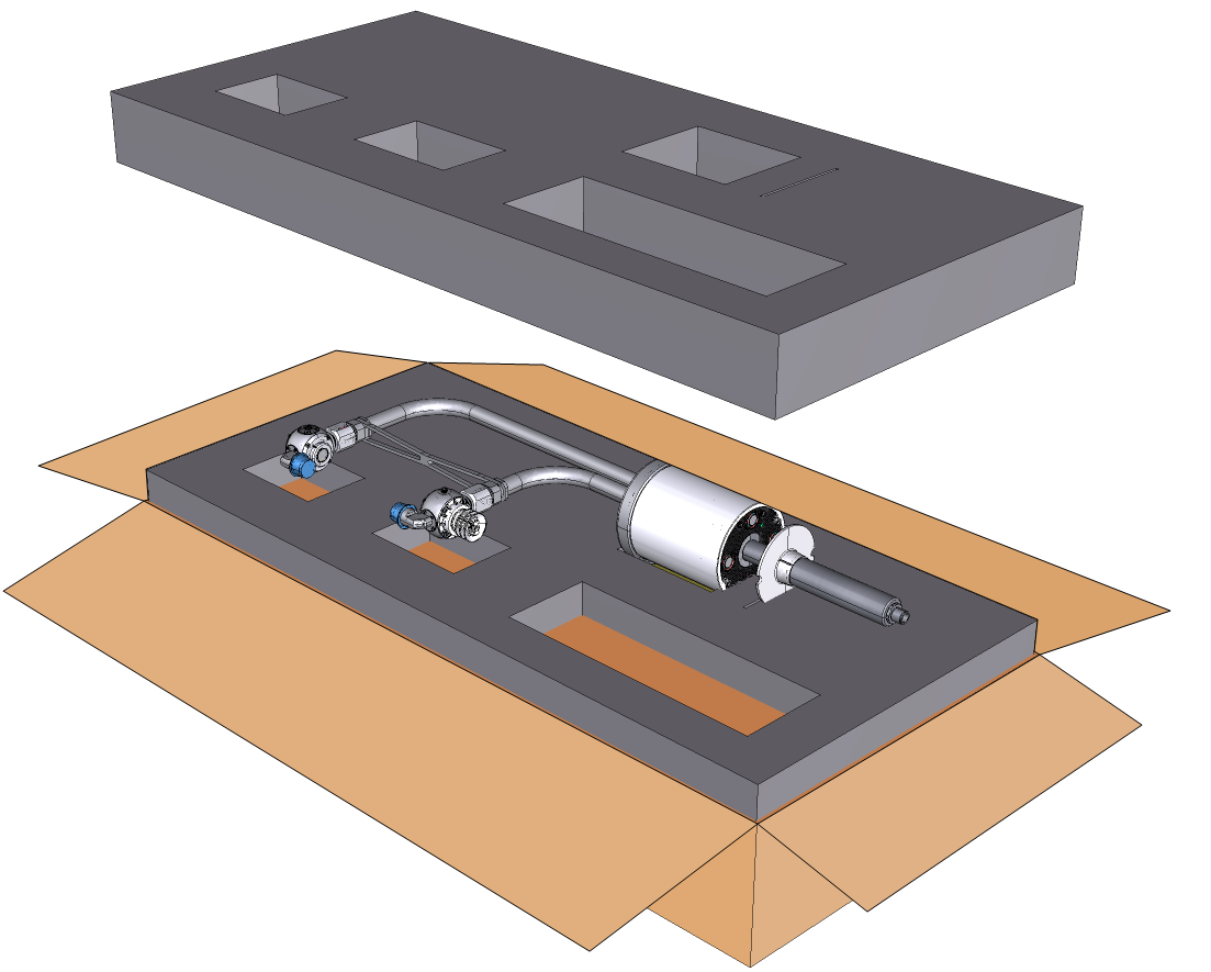
Shipping the LI-720
Keep the foam and cardboard packaging materials so you can ship and store the LI-720 safely. Always use the box and both foam pads to protect the optics.
IoE Module
The IoE Module should provide maintenance-free operation, typically. It has no user-serviceable parts inside besides the main battery and clock battery. If you encounter problems, contact LI-COR or your distributor for assistance. Some simple maintenance procedures may be needed when moving the IoE Module or when placing it into storage.
Disconnecting the solar panel
Read and follow all safety instructions provided with the solar panel. Do not disconnect the panel while it is under load. Cover the solar cells with a blanket or invert it so the cells are away from the sun to reduce the voltage output. Then disconnect the cables from the panel.
Replacing the Micro SD card
The Micro SD card reader supports the FAT32 and ExFAT. Any properly formatted card will work, so long as it has space for files. Other files can be on the card, but they take away storage space that would otherwise be available for data files. You can swap the card while the device is powered off, or use the mount/unmout button to swap the SD card while the device is powered on.
Removing the main battery
Power off the device. Hot swapping is not supported, so be sure to shut down the device before changing the power configuration.
Warning: The battery can explode, start a fire, or cause severe burns if the terminals are shorted together. Exercise extreme care when handling the battery. Use insulated tools when practical.
Caution: Cover the solar panel before disconnecting cables. Remove the solar panel power cables before disconnecting the battery cables. When disconnecting the battery, start with the black cable to reduce the risk of shorting the circuit.
-
Power off the device (press the power button, then select YES).
-
Cover or invert the panel to reduce its output, then disconnect one or both solar panel cables.
-
Remove the black cable from the battery post.
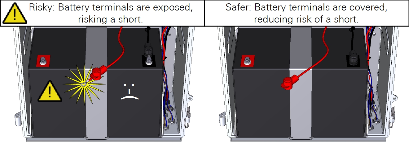
Remove the black one first to reduce the risk of shorting the circuit. Dangling cables may contact metal parts, causing problems. Avoid the problems by covering the contacts with the plastic covers to reduce risk of short.
-
After disconnecting a cable, slide the red and black covers over the metal contacts to reduce risk of a shorted circuit.
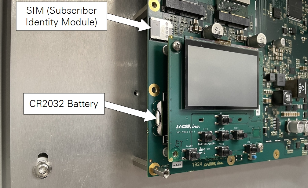
Replacing the coin-cell battery
A CR2032 battery is installed on the circuit board. This battery maintains the clock when power is off. If the IoE Module is unable to keep time while powered off, this battery may need to be replaced.
Caution: This procedure exposes the circuit boards of the instrument, which puts them at risk of electrostatic discharge (ESD). Work on an anti-static mat and wear an ESD wrist strap while performing this procedure.
To remove it:
-
Power off the IoE Module and disconnect the power supply and battery.
-
Remove the circuit board cover.
The battery is behind the display circuit board on the lower left side of the main board (Figure 8‑3).
-
Dislodge it with a non-conductive tool, such as a toothpick or stiff plastic coffee stirrer.
-
Replace the battery, then reinstall the cover.
Replacing the Subscriber Identity Module (SIM)
Note: Do not provide your own SIM. Contact LI-COR or your distributor if you need to replace the SIM.
The SIM is behind the circuit board cover (Figure 8‑3). To replace it, power off the device, remove the cover, slide the card out of the slot, and install the new one. After powering on the IoE Module, it will connect with the network automatically if the card is valid and the device has a cellular signal.
Caution: This procedure exposes the circuit boards of the instrument, which puts them at risk of electrostatic discharge (ESD). Work on an anti-static mat and wear an ESD wrist strap while performing this procedure.