Troubleshooting
Here we describe how to identify and resolve problems that may arise, starting with connection issues and finishing with diagnostic information.
LI-720 troubleshooting
Connection issues
Most connection issues can be resolved by checking the wiring connections or the data logger configuration.
- If connecting to a PC with the CarbonWare app, is it using the correct serial port?
- Typically, only valid serial ports are listed. You can try them one at a time or check the port number assignment in you computer Device Manager. To find the serial port number, open the Device Manager (press the Windows key
 , type Device Manager, then press Enter). Click Ports (COM & LPT). Look for USB Serial Port (COM#). The serial port numbers are shown beside the ports.
 - Power supply inadequate?
- If connecting to a PC with the USB cable, do not extend the cable. Voltage drops over a long cable can cause problems with the power supply (not enough power) or digital communication.
Measurement issues
- Air temperature and RH readings implausible or -9999?
- The sensor unit may have failed. See Replacing the air temperature and RH sensor.
Flux diagnostics
Before computing any results, the LI-720 filters implausible values from the 10 Hz raw data. A diagnostic code is provided for every computed result. The diagnostic code can reveal more about what was wrong with a particular measurement, details about environmental conditions for the time period, and information about the LI-720 performance over that time period. Some diagnostic codes are simply for your information - there is nothing to do besides know what the code indicates. Other codes may indicate that service is required. A few are reserved. A diagnostic code of 0 indicates normal operation.
Decoding the diagnostic
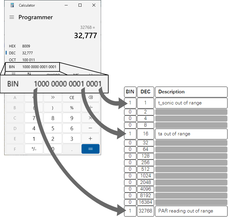
The diagnostic code is a 16-bit binary value encoded as a decimal value. It is included as the last parameter in output groups 0 and 1. The decimal value ranges from 0 to 65535 (corresponding to bit positions 0 through 15). It encodes up to 16 issues.
You can decode the diagnostic from decimal to binary using the calculator included with your computer operating system (Windows and macOS; select programmer mode). Enter the diagnostic value and observe the positions of the 0s and 1s in the binary results. Associate the 1s with the descriptions in Table 7‑1.
IoE Module troubleshooting
If you encounter unexpected performance or other problems with the IoE Module, start here to find a solution.
SDI-12 configuration problems
Configuration issues are related to communication between the IoE Module and attached sensors.
- SDI-12 devices not registered on the IoE module?
- Go through the steps in Configuring the Carbon Node to configure the sensors.
- Unsupported device?
- The IoE module supports the LI-710, LI-720, Stevens HydraProbe (firmware v4 and up), and Node Link (available on new IoE Modules indicated by the HOBOnet label and cable connector with firmware v1.2 or newer).
- Device cable disconnected?
- If a sensor has been configured but the cable is disconnected as you go through the configuration steps, the IoE Module will issue an error. Be sure the cables for all sensors are connected and select YES to try again.
Cellular or network problems
-
Adequate cellular signal strength?
-
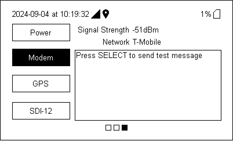
Be sure there is a strong cellular signal. If you are near the IoE Module, check the signal status on the IoE module. From the home screen, press right (
 ) and down (
 ) to view the status. You should see signal strength and the name of the cellular provider. A strong signal is close to 0 dBm, while a weak signal is close to -120 dBm. Press Select to send a test data message to LI-COR . If you see any message besides PASS, or if the signal strength is outside the expected range, contact LI-COR.
Problems powering on
Power supply problems can be resolved by checking the cable connections and voltage of the source. A multimeter may be useful for measuring voltages.
- Power cables connected properly?
- See Attaching the solar power supply or Using an external power supply.
- External power supply problems?
- If using an external power supply, be sure it provides 10 to 33 VDC with 3.0 amp capacity.
- Battery depleted?
- Measure the battery voltage with a multimeter. If it is less than 11 volts, the device will power off until the battery voltage is above 12. Allow the battery to charge from the solar panel or charge it with a compatible external charger. If the solar panel is not delivering enough power to charge the battery, clean it and adjust the angle and orientation so it faces the sun.
Classes and conditions
The device interface presents classes and conditions that indicate a problem. Classes are a category and conditions indicate the type of problem (see Table 7‑2). Press left ( ) once view Conditions.
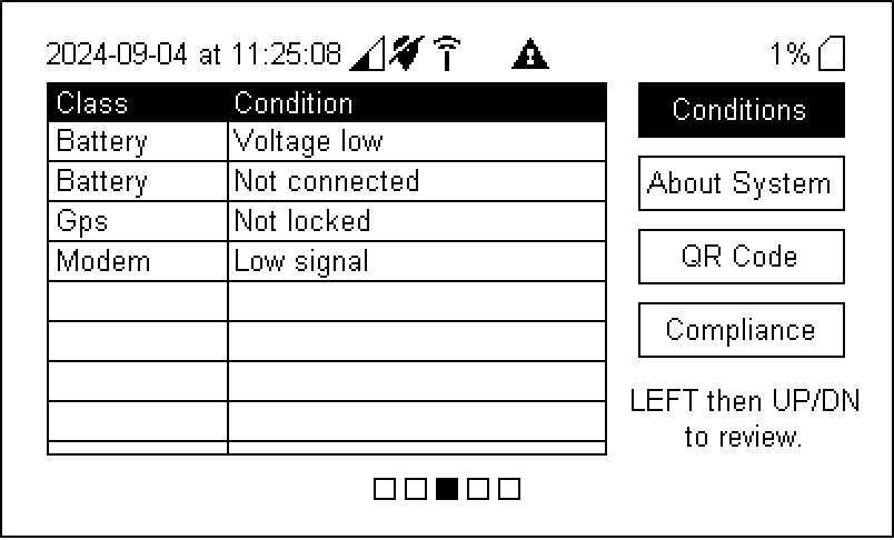
With the exception of conditions that are triggered during the startup cycle, conditions will remain visible on the display until cleared, even if the issue is resolved. This is intentional so that operators can observe conditions that have been triggered previously. Press Select to clear past conditions and show only current conditions.
| Class | Condition | Meaning |
|---|---|---|
| Battery | Battery not connected | No voltage measured from a battery. Check battery connections. |
| Battery | Voltage low | Critically low battery voltage. Apply external power or use solar charger. |
| Battery | Voltage high | Charger malfunction. |
| Battery | Load current high | System board malfunction; drawing too much power. |
| Battery | Charge current high | Charger malfunction; possible short circuit in battery system. |
| Battery | Rntc out of range | Internal temperature sensor malfunctioning. |
| Cloud | Can't connect to MQTT broker | Cellular data is fine but connection to cloud back-end was refused. Most likely a security problem. |
| Cloud | Last cloud session failed | There was a problem during the previous cloud session. This should resolve at the next cloud session. If this persists, there's something else wrong. |
| Config | Bad or missing SDI-12 network info | SDI-12 Network is not configured. Run the configuration tool. |
| Config | Bad or missing modem info | CRITICAL PROVISIONING FAILURE – important configuration data for cellular connectivity is missing1,2. |
| Config | Bad or missing cloud info | CRITICAL PROVISIONING FAILURE – device credentials for accessing the cloud service are missing1,2. |
| Config | No security certs | CRITICAL PROVISIONING FAILURE – device has no security certificates1,2. |
| Config | Bad or missing sensor info | Sensor configuration information missing (this is downloaded from LI-COR Cloud). This code should resolve itself at the next successful cloud session. Measurements cannot be obtained from a sensor with this problem. |
| Config | <sensor name> not supported | The named sensor is not supported by IoE. |
| Config | Bad or missing schedule | There is no schedule for measurements (run the configuration tool) or a schedule refers to a sensor for which configuration data is not available (should resolve at next successful cloud session). |
| GPS | Not locked | GPS location is unknown (also cannot synchronize to GPS time). |
| Logger | Card not mounted | SD card is either not present or was not mounted using the mount button3. |
| Logger | SD card FULL | SD card is <5% free4. |
| Logger | SD card nearly full | SD card is <25% free. |
| Logger | Sensor data cache nearly full | The IoE is nearly out of room to hold data in RAM. |
| Logger | Sensor data cache FULL | The IoE is out of room to hold data in RAM. If an SD card is mounted and not full, data is also backlogged there, so nothing will be lost in this case. |
| Modem | Can't connect to network | Modem cannot connect to cellular network. SIM card issue, perhaps. Maybe no coverage or signal strength issue. |
| Modem | Low or no signal | Cellular signal is critically low or no connection at all. |
| Modem | Modem unresponsive or missing | CRITICAL HARDWARE PROBLEM – cellular modem is malfunctioning. |
| SDI-12 | <sensor name> Read failure | Malfunction while reading this sensor. |
| SDI-12 | <sensor name> Sensor doc bad or missing | Sensor configuration data went missing. This is unexpected but should self-correct at the next successful cloud session. |
| SDI-12 | Bus voltage low | SDI-12 power supply malfunction or excessive load attached. |
| SDI-12 | Bus voltage high | SDI-12 power supply malfunction or possibly there is an external power source applied (don't do that). |
| SDI-12 | Bus current high | Excessive draw from attached SDI-12 sensors or wiring fault. |
| System | DEVICE MISSING SERIAL | CRITICAL PROVISIONING FAILURE – device has no serial number. This is indicative of acute system failure. Contact LI-COR. |
| System | No cloud connection since restart | This is a transient notice that simply lets you know the system has restarted and not yet successfully talked to the cloud service. |
| System | Scheduler halted | CRITICAL SYSTEM FAILURE – no measurements will be taken. Probably due to not being configured properly. |
| System | Uploader halted | CRITICAL SYSTEM FAILURE – no data will be sent to the cloud. If there is an SD card, CSV files will still be written and backlog data will be kept for when the uploader restarts. The uploader is halted by the configuration tool but should be running at all other times. |
Interface is unresponsive
If the IoE Module interface becomes unresponsive (no longer responding to button presses), and stays that way for more than a few minutes, you can force the device to restart.
-
Force power off: Press and hold the power button for 5 seconds. The IoE module will shut down inelegantly and open data files may be lost.
-
Disconnect the power supply: As a last resort, if the none of the buttons are responsive, disconnect the power supply for 30 seconds to a minute. Reconnect the power and allow a few minutes for the device to start. If the unresponsive behavior persists, contact LI-COR.
Persistent power cycling or unstable behavior
If you observe continuous restarts or unpredictable behavior in the interface that is not resolved by restarting the device, you can take more drastic measures and restore the IoE Module to the factory configuration.
Before doing this, however, check the power supply to make sure the IoE module is getting enough power to operate. If the battery voltage is close to 11 volts, it may be too low and the battery should be charged before attempting a factory reset. Check the cellular signal strength. Although poor signal strength will not cause power cycling, it could cause delays in the interface, which are easily confused with unstable behavior.
After verifying that the problem is unrelated to power or signal strength, factory reset may be the best option. Factory reset will clear everything from the IoE Module except the factory provisioning data (cellular network, LI-COR Cloud services, security credentials, device serial number).
To perform the factory reset:
-
Power-off the device.
-
Press and hold UP and MOUNT/DISMOUNT simultaneously.
-
While UP and MOUNT/DISMOUNT are pressed, short-press the POWER button.
-
Continue to hold UP and MOUNT/DISMOUNT until the screen with the version info below the product name is displayed.
-
Release all buttons and allow the IoE module to finish starting up.
-
After resetting, you must re-configure SDI-12 sensors and schedules.
Carbon node sensor network issues
This section describes some steps you can take to resolve problems with the HOBO link and Node Link devices. If you have trouble with the Carbon Node Sensor Network, start by reviewing Tips for wireless sensors. If you are unable to resolve any issues, contact LI-COR or your representative.
Sensor not appearing in the Device Setup list
-
Being impatient?
-
Each RX sensor may take up to 5 minutes to register with the Node Link. You may just need to wait a little longer.
-
Batteries depleted or installed incorrectly?
-
Verify that the batteries are installed correctly. Then, expose the solar panel to sunlight for a few minutes.
-
Out of range?
-
During the registration process, keep each sensor close to the Node Link. After registering successfully, you can position sensors up to 200 meters from each other. Sensors can transmit data through each other (up to 5 hops) for a maximum total distance of 1500 meters.
LI-COR Cloud issues
If you configured everything but do not see data on LI-COR Cloud, you may just need to wait at least 10 but possibly 30 or more minutes for results to be published. As you wait, you can check the status on the IoE Module display. It is normal for several messages to be in the queue, but if there are many and the number is increasing over time, there may be an issue.
Check the SDI-12 configuration. From the home screen, press right once and down three times to select SDI-12. Press Select and the IoE Module will scan all SDI-12 ports and report the status. It will give Last Seen and the time of that communication. The time indicated should be recent, and if so, everything is working, and you should just wait for the data to be presented on LI-COR Cloud. See SDI-12 status for more details.
Finally, be sure that the IoE Module has been registered with LI-COR Cloud and that you have an account that allows you to view data from this IoE Module.