
Troubleshooting
If you are having issues that are not indicated by the messages, look in this section for solutions.
Can't copy files using USB
If copying files, be sure the head and console are both connected via the head cable. The USB device must be formatted as a FAT (File Allocation Table) file system. See Transferring files to a computer for more options and tips.
The log button on the head does not work
- Log file open?
- A log file must be open to record data.
- Pressing long enough?
- Press and hold until it logs the value. Holding the log button will only log a single point.
CO2 cartridge exhausts quickly
- Is the cartridge holder tight enough when a new cartridge is installed?
- Tighten it firmly to ensure a good seal.
- Dirt in the threads?
- Check the threads for dirt or debris and clean them if needed.
- Missing O-ring?
- If the white O-ring around the piercing pin is missing, a replacement is in the spares kit (part number 192-14864).
- Wrong size cartridge?
- Be sure to use 7.5 or 8 gram cartridges. If the cartridges are too small and tightening the holder firmly does not stop a leak (or pierce the tip) try dropping a small coin or washer into the holder before inserting the CO2 cartridge.
Issues with environmental controls and setpoints
This category of issues is related to setpoints and controls for the sample environment.
Environmental control setting is being overridden
This can happen under a few circumstances:
- Is the instrument in the middle of the system tests?
- You can wait until it is done or cancel the test.
- Is it running an Auto Control?
- Disable the Auto Control.
- Is it running a Program?
- Disable the Program.
- Has it overridden a humidity setpoint to prevent condensation?
- If the humidity gets too high in the chamber, heat exchange, or IRGAs, the instrument will override the setpoint to protect itself from condensation. The controller will overshoot the setpoint a little when changing temperature to shorten response time but, in the process, may get to condensing conditions. To avoid this, you can choose a drier setpoint briefly while the system is cooling down. Then, select a wetter setpoint.
- Is it changing the temperature source?
- It has detected an implausible reading from the sensor. Check to see that the thermocouple is plugged in. See if it still works. You can also try swapping which port (T1 and T2) the thermocouple is connected to and try using a spare thermocouple from the spares kit.
Instrument does not respond after entering a flow setpoint
- Flow on?
- Under Environment > Flow, be sure the pump is on. It won't necessarily turn on when you start a Program or Auto Control. Also be sure that there is flow going through both reference and sample IRGAs. You can try to increase or decrease the flow or try another pump speed. Auto is always a safe choice for the pump speed.
Cannot maintain CO2 setpoint
- Run the CO2 limits and match test.
- If the instrument passes the test without warnings or failures, you may need to flush the desiccant and humidifier columns since they both can hold onto and release CO2 (especially silica gel). With the CO2 injector set to On and either CO2_s or CO2_r set to 0, manually control the humidifier and desiccant at 100%. Watch CO2 drop; when CO2_s and CO2_r are both close to zero, resume normal operation.
- Chemicals fresh?
- When the soda lime is saturated, you may see oscillations in CO2_r as small as 2 to 5 µmol mol-1, or much greater. You can usually get a few minutes of stable operation by shaking up the columns, but the best solution is to replace the depleted chemical with fresh. If the Stuttgarter Masse is too wet, you may see unexpected fluctuations in the CO2 reading.
- Does the cartridge contain a gas other than CO2?
- Some 8-gram cylinders contain gases other than CO2. If the cylinder is not labeled and you are unable to verify its contents, remove it and install a cylinder that definitely contains CO2 gas.
- Problematic CO2 regulator or plugged capillary tube?
- If the previous steps have failed to resolve the issue, you may need to observe some internal operating parameters. See Testing the regulator and capillary tubes.
Testing the regulator and capillary tubes
- Download the firmware updater from licor.com/support/LI-6800/software.html.
- If you have an updater already, you do not need to get it again; any version will work for this.
- Connect the LI-6800 to your computer or network using an RJ-45 network cable, launch the LI-6800 updater, double click the console serial number to connect, and then double click CO2_flow in the new window.
- That will bring up graph of CO2_flow as voltage vs. time.
- Install a fresh CO2 cylinder - this procedure will have different results if there is no CO2 supply.
- Configure the settings.
- Pump = Medium
- Flow = 500 μmol s-1
- While observing the graph of the voltage over time, change the CO2 injector settings from 100% to Off.
- 5 V at both 100% and Off indicates normal operation.
- 2.5 V at 100% and 5 V at Off indicates a clogged capillary.
- 2.5 V at both 100% and Off indicates a regulator issue.
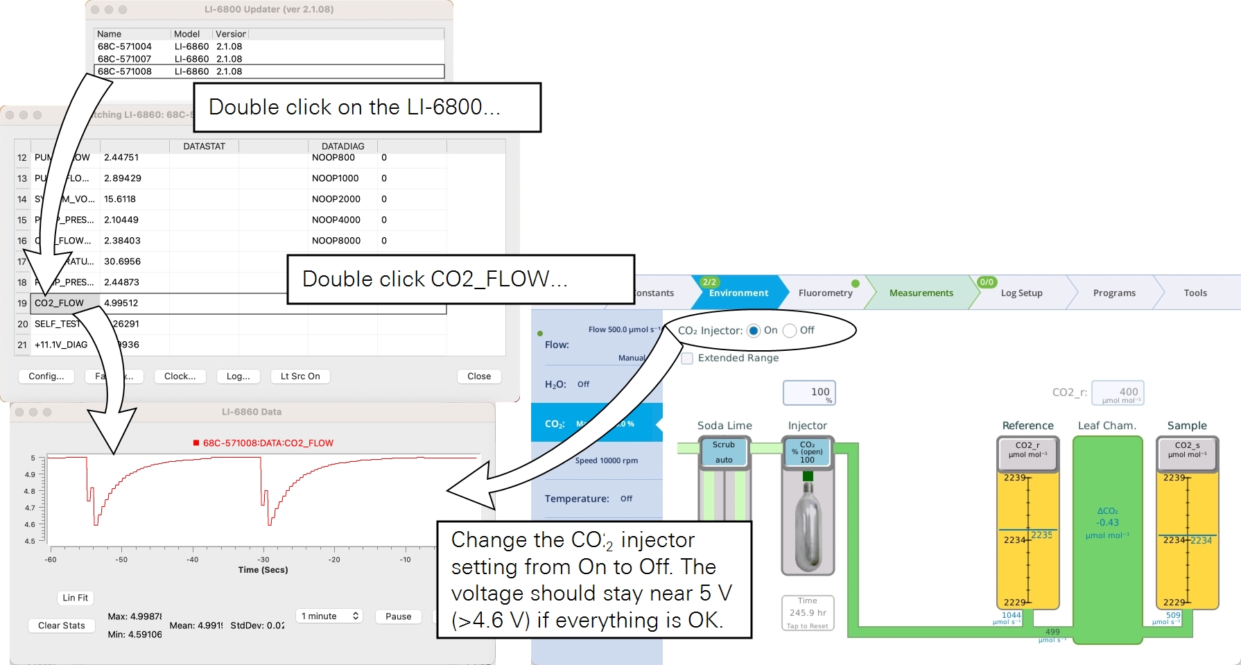
- While testing this, also make note of the CO2_r concentration.
- At Pump = Medium, Flow = 500 μmol s-1, CO2 Injector = 100%, Soda Lime = Scrub, CO2_r should be about 2200 µmol mol-1. Allow a few minutes for the instrument to pressurize before recording this value. If the instrument has a clogged capillary, regulator issue, or the maximum CO2_r value is significantly below 2200 µmol mol-1 CO2, it will need to be repaired. Contact LI-COR or your distributor for an RMA.
Cannot achieve flow setpoint
- Flow meters need to be zeroed?
- Zero the flow meters under Tools > Calibrations > Flow/Pressure.
- Leak in the system?
- Run the pump speed test. If it fails, investigate to find the leak. See Instrument fails the leak test.
Cannot maintain humidity setpoint
- Substrate too dry?
- With the older Pall Stuttgarter Masse crushed ceramic substrate, check to see if it is adequately moist. Add 5 to 10 ml of water to each side if it is dry. With the newer Nafion column, be sure there is water in the column. See Filling the columns for details.
- Humidifier column or desiccant column filters clogged?
- Check the filters on the humidifier and desiccant columns. If they are visibly soiled, replace them with filters from the spares kit (see Column air filters).
- Poorly zeroed IRGAs?
- If an H2O zero was performed at some concentration that is not zero, the H2O variables will always look lower than they are and it might not look like you are reaching a low enough VPD or high RH. If this is a concern, reset to the factory calibration to see if that helps.
- System tool warm or cold?
- If the system cannot humidify the air to the requested setpoint, consider decreasing the chamber temperature (Tair). If you need the chamber to be warm, consider increasing the temperature where your console (humidifier column) and sensor head is located. The closer the whole system is to thermal equilibrium the easier it is to increase humidity.
- Alter the flow rate.
- A higher flow rate will flush the chamber faster resulting in lowered humidity. Similarly, you can lower the flow rate to increase chamber humidity.
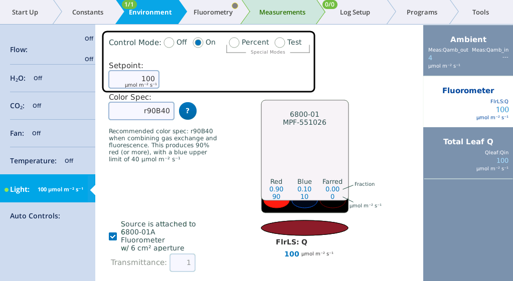
Cannot control the fluorometer output
- Symptom: LI-6800 The fluorometer does not output any light no matter the setpoint.
- Possible solution: Be sure the control mode is On and a Setpoint is set.
- Symptom: The light output does not change even with a new setpoint value. The system is very sluggish. The LI-6800 also issues frequent warnings about clocks being out of sync and attempting to sync head and console clocks does not help.
- Possible solution: Connect your instrument to a network and restart the instrument. Check to see if you can control the setpoint. If you can, it is likely that the fluorometer clock battery needs to be replaced. See Replacing the fluorometer coin cell battery.
Fluorometer does not flash on log
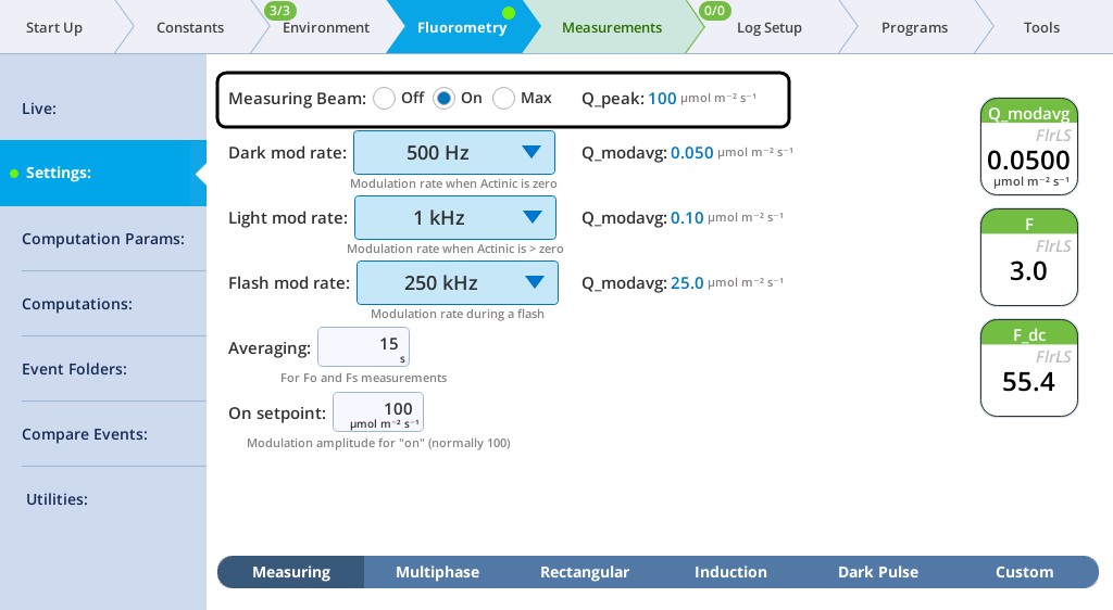
- If the LI-6800 fluorometer does not flash on log, is the Measuring Beam is set to On?
- Change the setting under Fluorometry > Settings > Measuring.
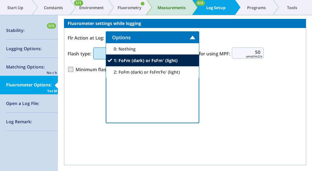
- Is the fluorometer set to do 1: FoFm (dark) or FsFm' (light) or 2: FoFm (dark) or FsFm'Fo’ (light) on log under Log Files > Fluorometer Options?
- If it is set to 0: Nothing, no flash will occur upon logging. Also review the Minimum flash interval (if checked) to make sure it is set to a reasonable value. Clear the check box for testing purposes.
- Is the fluorometer clock out of sync?
- If the fluorometer clock keeps un-syncing, its clock battery may need to be replaced. See Replacing the fluorometer coin cell battery.
Chamber and light source warning messages
There are warning messages that will be triggered if there is a mismatch between that information and the information stored on the chamber. This can be caused by manually entering incorrect chamber info or if the chamber memory becomes corrupted somehow.
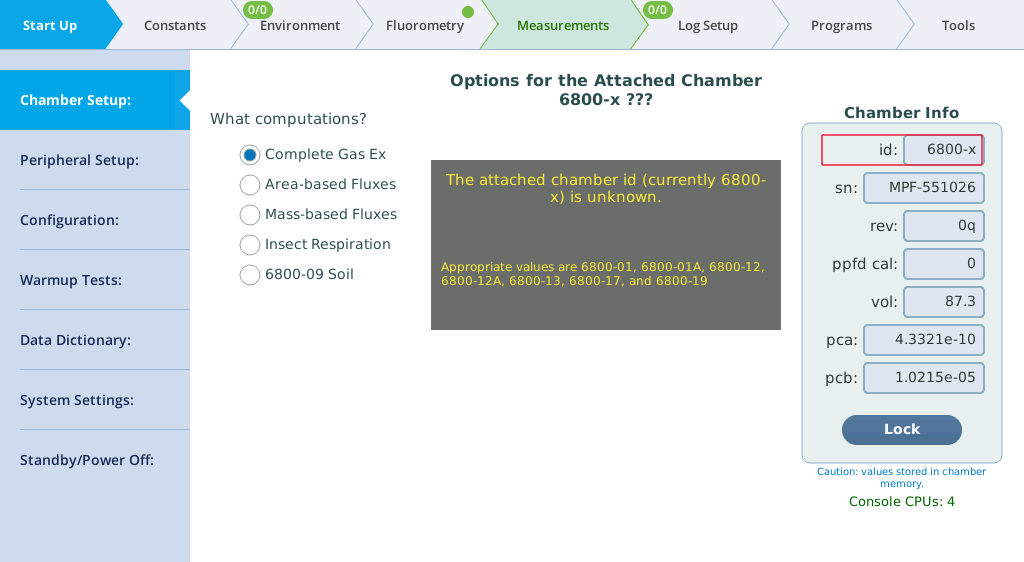
- Unknown chamber warning
- If triggered, the chamber id box is highlighted in red. That is where you fix the problem.
- Missing fluorometer warning
- This issue is most often related to a communication error between the fluorometer and the console.
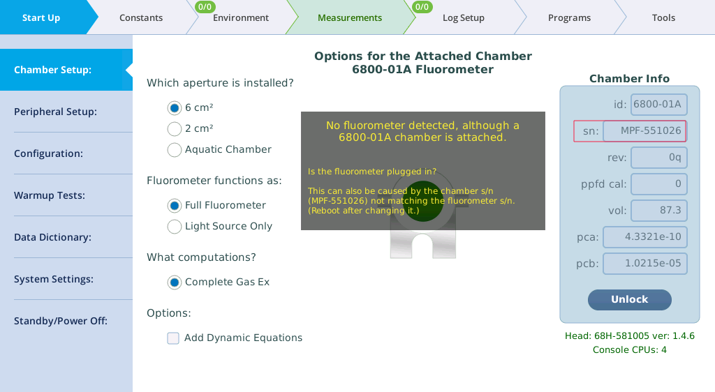
Solutions:
- Wait a few minutes.
- The instrument may need to finish starting up; restart the LI-6800. Sometimes it goes away on its own if you wait a minute or two.
- If that does not help you can either
-
- Disconnect and reconnect the fluorometer cable from the console. In this case, wait about 30 seconds for the fluorometer to show up.
- Restart the instrument.
- If none of the above helps, you may have a chamber serial number mismatch.
- Make sure the chamber sn box highlighted in red contains the correct serial number. If it does, there is still a chance that the fluorometer thinks it has one serial number while the sensor head thinks the fluorometer has another serial number. The following steps will ensure they both have the same serial number in place:
- Make sure your computer and LI-6800 are on the same network.
- Open up the LI-6800 firmware updater (it does not have to be the most recent updater) and select your instrument in the list.
- Click Advanced and check Display Extended Info.
- Click the fluorometer entry (named like MPF-xxxxxx) to see its information.
- If you cannot see the fluorometer in the list but you are certain that the fluorometer is connected, your fluorometer is not powering up. Contact LI-COR or your distributor for support.
- Make sure the serial number (sn) in the list matches what is printed on the fluorometer serial number label. If it does not match, enter the serial number Chamber Info > sn and tap Done.
- Click on the 68H-xxxxxx to see the head information.
- The fifth item in the list (chamber) is the chamber serial number. Verify that it is the same as what is printed on the fluorometer serial number label.
If for some reason the fluorometer still is not recognized, contact LI-COR or your distributor for support.
- Unexpected fluorometer warning
- If this happens, the chamber id box is highlighted in red.
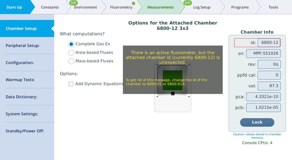
It is likely because the chamber id is not correct. Follow the on-screen directions to correct the issue.
Chamber leak warning message
- Chamber closing properly?
- Open and close the chamber a few times to make sure the mechanism is working correctly.
- Leaf gaskets compressed, torn, or damaged another way?
- Replace if necessary.
Instrument fails the leak test
-
Column leaking?
-
Check for cracks in the walls or caps of the chemical columns. There are replacement chemical column caps (6368-495) in the spares kit.
Leaks usually come to your attention by causing a leak test, flow test, or pump test failure (Start Up > Warmup/System Tests), low Flow reading (mass flow to chamber), or a low Flow_s or Flow_r reading (flow through the sample/reference gas analyzer). Also, one of the following warning messages may appear on the upper left corner of the display: Console Flow Leak?, Flow_s Low, or Flow_r Low.
- If you can achieve the Flow setpoint, but Flow_s is near zero or much lower than the flow to the chamber, it is likely a chamber leak. Check the following things:
-
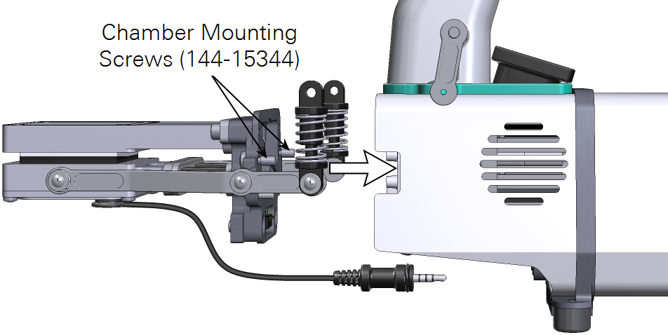
- Make sure that the chamber is installed tightly enough with two Philip screws (part number 144-15344) and adequately closed.
- Check the leaf gaskets on the chamber. If the gaskets are flattened or torn, change them. Black neoprene gaskets can recover if left uncompressed overnight, but the white foam gaskets may not. Advanced polymer gaskets recover more quickly.
-
- Spare gaskets are included in the chamber spares kit. See Gasket replacement for details.
-
- Make sure that the thermocouple is installed and the O-ring (part number 192-14435) on the chamber bottom that seals the thermocouple is in place.
- The lower chamber may have two flexible black ducts (depends on chamber type, part number 6368-345). They may wear out over time. Change if necessary. Damage to the ducts should rarely happen, but if they are kinked during removal or installation, they may develop leaks. Ensure that the bead of the duct seats in the groove.
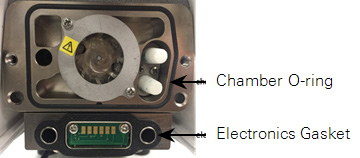
- Remove the chamber from the head and you will see the big chamber O-ring (part number 192-14438) and electronics gasket (part number 6568-327). Replace them if damaged.
- If using the leaf chambers that have the removable aperture inserts (6800-12A & 6800-01A), check if the apertures are seated firmly in the top and bottom chambers. Make sure the aperture O-rings are in place and good condition.
-
- Spare O-rings are included in the chamber spares kit. See Chamber O-rings and gaskets for details.
-
- Change the chamber overpressure (ΔP) setting (Environment > Flow) to 0 kPa or 0%. If that results in an increase of the Flow_s or decrease of the percentage of apparent leak, run the Pressure Valve test under Warmup Tests. If the test fails, contact LI-COR.
- If Flow_s / Flow_r is low and Flow cannot reach its setpoint, check the following:
-
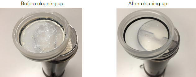
- Make sure the humidifier and desiccant columns (part number 9968-225) are present and securely attached to the console (they should be removed during transportation and storage). Check if there are any cracks in the walls of the chemical columns.
- Check to see if any chemical debris or anything else has accumulated on the threads of the cap and the tube. This will prevent the cap from getting a good seal. This may especially be the case with the Stuttgarter Masse column, where difficult-to-see ceramic particulates can accumulate. Wipe the threads, rim, and O-ring with a moist paper towel to remove any debris. This will also help keep the column and cap from being damaged by the coarse debris.
-
- To isolate a leak to either the humidifier or desiccant tubes, try replacing the tube in question with the soda lime tube (the soda lime position can remain empty – it is on the vacuum side of the pump so will not cause a leak). If that fixes the leak, you have found the culprit.
- Make sure that the O-ring (part number 192-14541) inside the bottom column cap is in place.
- Each chemical column has two filters (part number 300-14319) held in place with rubber seals (part number 6368-225). Check if any of the two air filters are missing.
- Make sure that the air supply tube is securely connected to the console outlet and sensor head inlet. Hold onto the Bev-a-line tubing (not on the Quick-connect Coupler) and pull. It should not come loose. If it does, firmly reconnect it (make sure the Quick-connect Coupler is pushed in to the end until you hear a click sound). Continued failure may indicate a new Quick-connect Coupler (part number 300-07125) is needed. Check each end of the air supply tube.
- If the Pump Speed Tests fails but you cannot identify the leak, go to Environment > Flow and set the flow split to 100% with the chamber closed. Step through each of the pump speeds and register the Flow, Flow_s, and Flow_r. If, for any of the pump speeds, the following condition is true:
- Flow_r is ˜0 but Flow and Flow_s are both low, you still have a console leak.
- Flow_r is >= 50 µmol s-1, you may have a valve leak.
- Flow = 0 or 2400 µmol s-1 while Flow_s is increasing with increased pump speeds, you may have a failed flow sensor.
- Conditions B and C both require service at LI-COR.
Pump/flow meter issues
Version 1.5 adds some tools for helping diagnose pump / flow meter issues. These are Background Programs (BPs) that can be found in the /home/licor/apps/tech/ directory.
A suggested work flow when dealing with pump / flow meter issues:
- The fundamental test is the Pump Speed test in the Warmup/System tests.
- If the test doesn't pass with the chamber closed, try opening the chamber and re-running it. If it passes then, it suggests an obstruction in the head, such as clogged air filters.
- If the flow rate doesn't change with pump speed (stays maxed out, for example) it suggests a failed flow meter. It could also be due to faulty pump control settings; to check that possibility, do step #2.
- If the Pump Speed test indicates that some of the pump settings are producing flows not in the expected range, continue with step 3.
- Run the BP PumpCalCheck.py (described in PumpCalCheck.py).
- If there are suspicious values, tap the Fix button to fix them. Retry step 1
- If no issues are reported, but you had issues in step 1b, then the flow issues are likely due to the flow meter, not the pump.
- Load the BP CalibratePumpSettings (described in CalibratePumpSettings.py) into the BP build environment. This will allow you to see the log output and the graphic output. Open the chamber to remove potential flow constrictions. Then Start it. Possible outcomes:
- Aborts with one of the following messages:
- PROBLEM: Flow not increasing with pump speed.
- PROBLEM: Lowest flow > minimum target.
- PROBLEM: Highest flow < maximum target.
- PROBLEM: Unexpected pump or flow meter behavior.
- All would indicate some problem with the pump or flow meter. Contact LI-COR.
- Finishes. If the resulting plot looks like the expected plot (Figure 6‑5), keep the result. If there is something suspicious, revert to the old values.
- Aborts with one of the following messages:
PumpCalCheck.py
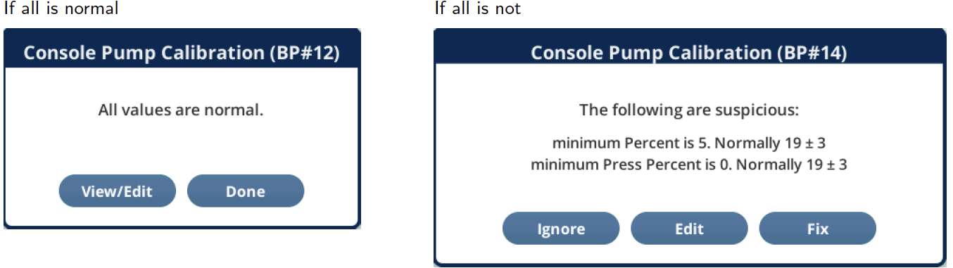
The PumpCalCheck program checks the current pump calibration values. If any are more than 3 × the ± value away from the typical value, they are flagged. Otherwise, they are reported as normal (Figure 6‑2).
The Fix button sets the offending values to typical. The View/Edit button launches PumpCalEditor.py.
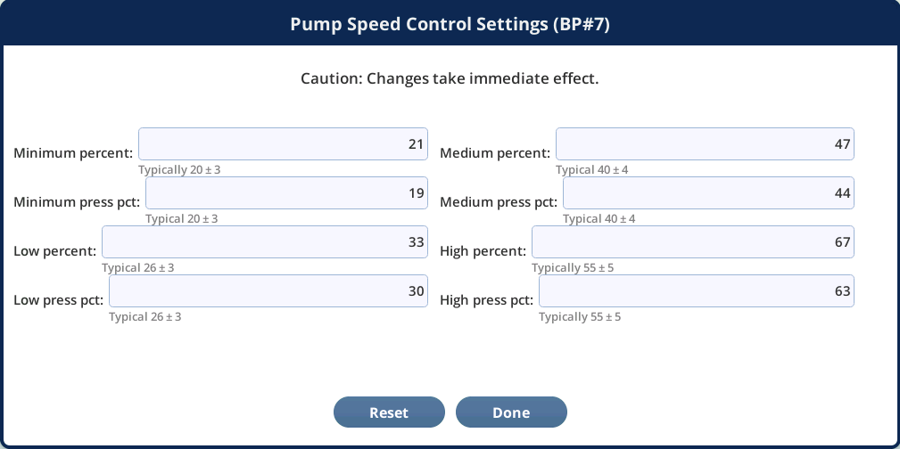
PumpCalEditor.py
The PumpCalEditor program allows direct editing of the pump calibration settings. The Reset button sets them all to the "Typical" values. "Typical" does not mean "Must be within this limit". There may be reasons why a particular unit has values outside this range. However, once the values are beyond 5 times the specified range, that could merit attention. Run the CalibratePumpSettings program (see CalibratePumpSettings.py) to either correct or verify the settings.
CalibratePumpSettings.py
This test runs a calibration to pick pump settings for the four standard speeds (minimum, low, medium, and high). A functioning flow meter is an absolute necessity, and if flow meter behavior is deemed suspicious, the test is aborted. An open chamber is not necessary, but if there is a blockage downstream of the chamber (e.g. air filter, pressure valve stuck shut, etc.), an open chamber avoids that issue.
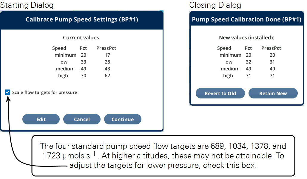
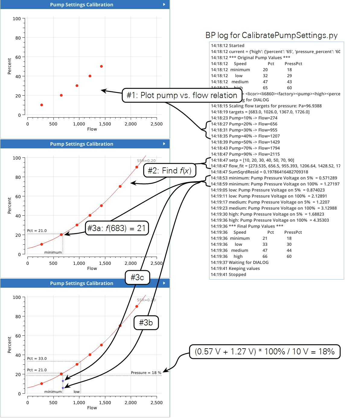
The program CalibratePumpSettings uses the BP Outputs page (Figure 6‑5) to show progress as it works through the calibration algorithm. That table to the right shows before and after calibration settings.

CalibratePumpSettings Details
First, the relationship between the pump’s power setting (P) and actual flow rate (F) is determined over a range of (P), from 10 to 90% and measured and plotted (Figure 6‑6 #1). If each pump setting does not result in a flow of at least 100 μmol s-1 greater than the previous, the test will abort with the message
PROBLEM: Flow not increasing with pump speed.
If the measured flow range does not capture the desired flow range (targets), one of the following messages will be displayed, and the test aborted.
PROBLEM: Lowest flow > minimum target.
PROBLEM: Highest flow < maximum target.
A 2nd order polynomial fit (f(x)) of (P) as a function of (F) is determined (#2). We plot and fit the relationship “backwards” (pump power as a function of flow rate) because we want to be able to look up (f(x)) the necessary pump control to provide the desired flow rate. If the fit is too poor (sum of residuals squared >10), the test is aborted with the message
PROBLEM: Unexpected pump or flowmeter behavior.
Once the pump control relationship is known and seems reasonable, for each of the four pump settings (minimum, low, medium, and high) the following sequence is performed (Figure 6‑6 #3):
- The pump setting is obtained from (f(x)). In , Figure 6‑6 step #3a illustrates this for
minimum: the target flow is 683.0 μmol s-1, and (f(683) = 21), rounded to an integer. - The pump is set to this control setting.
- The pump pressure control is set to 5%, and a reading of pump pressure (p1) is made (in Volts). (#3b in the example).
- Repeat for pump pressure control set to 100%, measuring (p2) (#3c in Figure 6‑6).
- The pump pressure setting is (p1 + p2), converted to percent (100 % = 10 V).
- Repeat for
low,medium, andhigh.
The pressure readings, (p1) and (p2), come from the key PUMP_PRESSURE in topic licor/li6850/output/DATACONSOLESTAT.
Unreasonable results
The first indicator of trouble, to those who are new to gas exchange, will typically be the values that the user is paying attention to: photosynthesis, conductance, Ci, or others. The tendency may be to blame the computer, but usually it is just doing what it is told, and the unbelievable results are coming from unbelievable inputs. You will need to look behind the computations and determine which input is unbelievable and why. If photosynthesis seems to be jumping around, try these suggestions:
- Are you being impatient?
- Right after a change in input conditions, such as a big change in the CO2 control setting, there will be a short period (up to 2 minutes) where the photosynthetic rate will be nonsense until the gas analyzers achieve the new equilibrium values.
- What is the magnitude of the variation?
- There will always be some variation in the displayed value of any measured or computed quantity. Is the variation excessive? Is it due to normal noise of the analyzers? Remember that at low photosynthesis rates, the noise in the CO2 differential will become more and more significant. So, is the variation in ΔCO2 greater than 0.1 µmol mol‑1?
- Watch those flow rates.
- For purposes of troubleshooting, operate with a fixed flow rate.
- Is the input stable?
- Watch the reference CO2 (CO2_r) for 15 seconds. How much does it vary? Expect variations near 0.1 µmol mol‑1 at ambient concentrations. If it is much more than that, you may have a problem, such as old soda lime.
- Are the sample measurements (CO2_s) stable?
- If the reference values are stable, but the sample values are not, there could be leaks between the leaf and chamber gasket. This can happen if the leaf has large veins, for example.
Touchscreen not responding
If the head cable becomes disconnected from either the head or console while the instrument is powered on, parts of the interface will become unresponsive. Power off the instrument by pressing and holding the power button for about 5 seconds. Reconnect the cables and power the instrument back on. If the problem persists, contact LI-COR.
Power on problems
There are no user-replacable fuses in the instrument. If you suspect that a fuse has blown contact LI-COR or a LI-COR representative.