Assembling the IoE Module
The following steps can be undertaken indoors or outdoors. If it is your first time with an IoE Module, you may find it worthwhile to do this in the comfort of your office, and then you'll know exactly what is needed for your work in the field.
Unpacking the boxes
The hardware is shipped in corrugated cardboard boxes with cardboard sheets, boxes of components, empty boxes, and foam blocks to secure components while in transit. Unpack the hardware before going to the field. Be careful to avoid discarding hardware when you discard the packaging materials. Some packaging materials are hard to remove while the frame is collapsed; remove them when you unfold the frame. Use a box cutter to open packaging and a clippers to cut zip ties used in packaging.
- Set the large box on the ground in your workshop, lab, or office.
- Cut all of the tape on the seams and unfold the cardboard.
- Lift off the loose pieces of cardboard to expose the solar panel box.
- Continue to remove spacer boxes and boxes of parts until they are all separated from the packaging.
- Open every box and separate the packaging materials and filler until you have identified every component included in your order.
Warning: The components of this product are heavy (see Specifications for weights). Use caution to avoid injury when lifting and securing components. Moving the fully assembled product should not be undertaken without appropriate precautions (e.g., a mechanical lift system, two-person lift, or other suitable lifting method).
Check the lists of components in IoE Module.
Installation considerations
In this section, we describe how to deploy the system, with a focus on the hardware installation and assembly.
Assembly time and personnel
Be prepared before starting to install the device. Gather tools in advance. Allow at least three hours to unpack and assemble the structure. Components are heavy and bulky; at least two people should transport and set it up.
User-supplied installation tools
You will need a number of tools for the installation:
- Adjustable wrench.
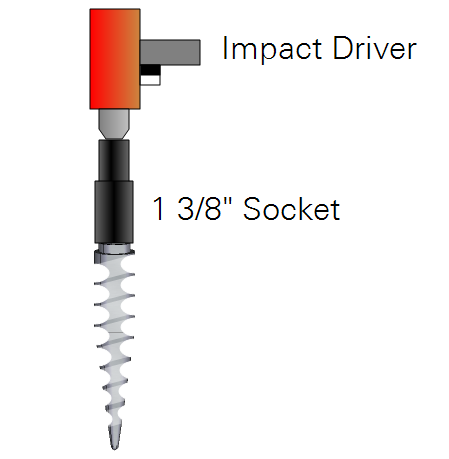
- Impact driver with a 1 3/8" six-point socket to install the earth anchors, although you can install them by hand using the ground rod as a lever.
- Sledge hammer or hammer drill with a ground rod bit to install the ground rod.
- Red or reflective tape to mark guy wires and call attention to trip hazards.
- Zip ties or hook-and-loop cable ties to secure cables.
- Angle gauge or cellphone with level app to estimate the angle of guy wires.
- Sturdy gloves and safety goggles.
Site inspection
It is critical that you know of any underground utilities that are installed at your site. Local laws may require an inspection before installing the ground rod. In the USA, call 811 to arrange a site inspection. Check for unexploded ordnance, gas lines, water lines, sewer lines, pipelines, electrical wires, fiber optics, or any other underground infrastructure before installing the ground rod or earth anchors. The rod may extend up to 1.5 meters (5 feet) into the ground. The earth anchors may extend up to 35 cm (14 inches) into the ground. Failure to check may result in bodily injury, death, damage to infrastructure, or damage to equipment.
Vertical and horizontal clearance
Do not install the device near overhead power lines. If using the guy wires, allow clearance around the mast that is equal to the height of the mast. For example, fully extended to 5 m (15 feet), ensure a radius of the same distance around the mast remains clear for the guy wires.
Soil characteristics
The earth anchors are designed for hardpan, dense sand or gravel (class 1), medium sandy gravel (class 2), loose medium-to-fine sand (class 3), or loose, and fine uncompacted sand (class 4). Earth anchors may not anchor in some soil types. If the soil is unsuitable, choose an alternative anchor or a different location.
Prepare for field deployment
If you did the initial assembly and configuration in an office or lab, partial disassembly of the hardware will make it easier to move to the field.
- Power off the IoE Module.
- Disconnect the sensor cables from the IoE Module. Keep track of which sensor is connected to which connector, you'll need to connect them the same way or repeat the steps in Initial setup.
- Remove the battery (see Removing the main battery).
- Remove the four nuts and bolts that were installed in the frame rails and fold the frame. Keep the nuts and bolts for reassembly.
- Gather your tools and hardware. Get some water, a snack, and put a smile on your face. It'll be a good day!
Initial assembly
Warning: The components of this product are heavy (see Specifications for weights). Use caution to avoid injury when lifting and securing components. Moving the fully assembled product should not be undertaken without appropriate precautions (e.g., a mechanical lift system, two-person lift, or other suitable lifting method).
Mast and frame
Caution: Wear gloves and goggles for safety.
-
Remove and discard the black caps from the top and bottom of the mast.
-
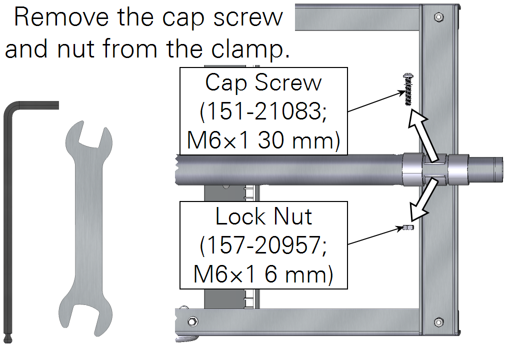
Release the upper mast clamp.
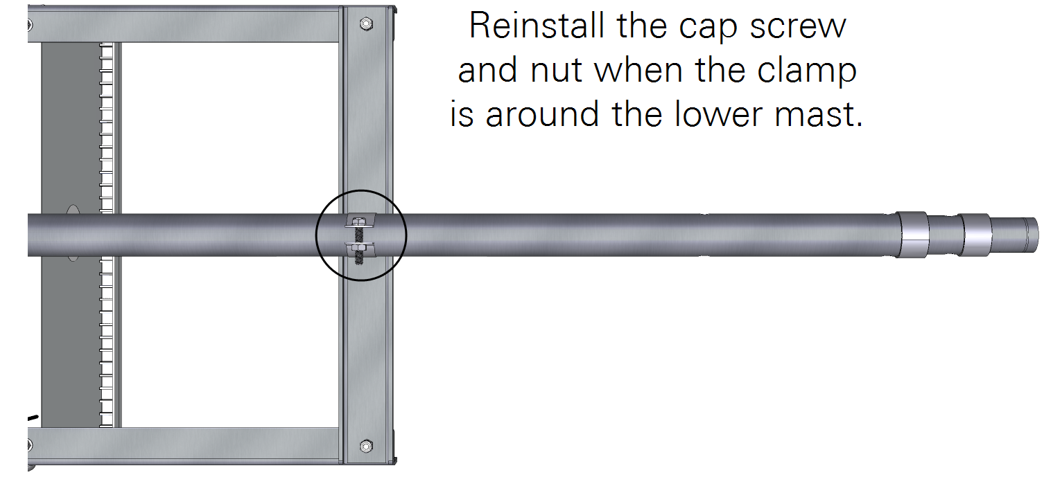
Remove the nut and cap screw that secure the mast, and then pull the mast out of the bracket. Slide the mast up and then press the largest section of the mast into the clamp. Then reinstall the hardware.
-
Extend the mast so the bottom is aligned with the lower rail.
-
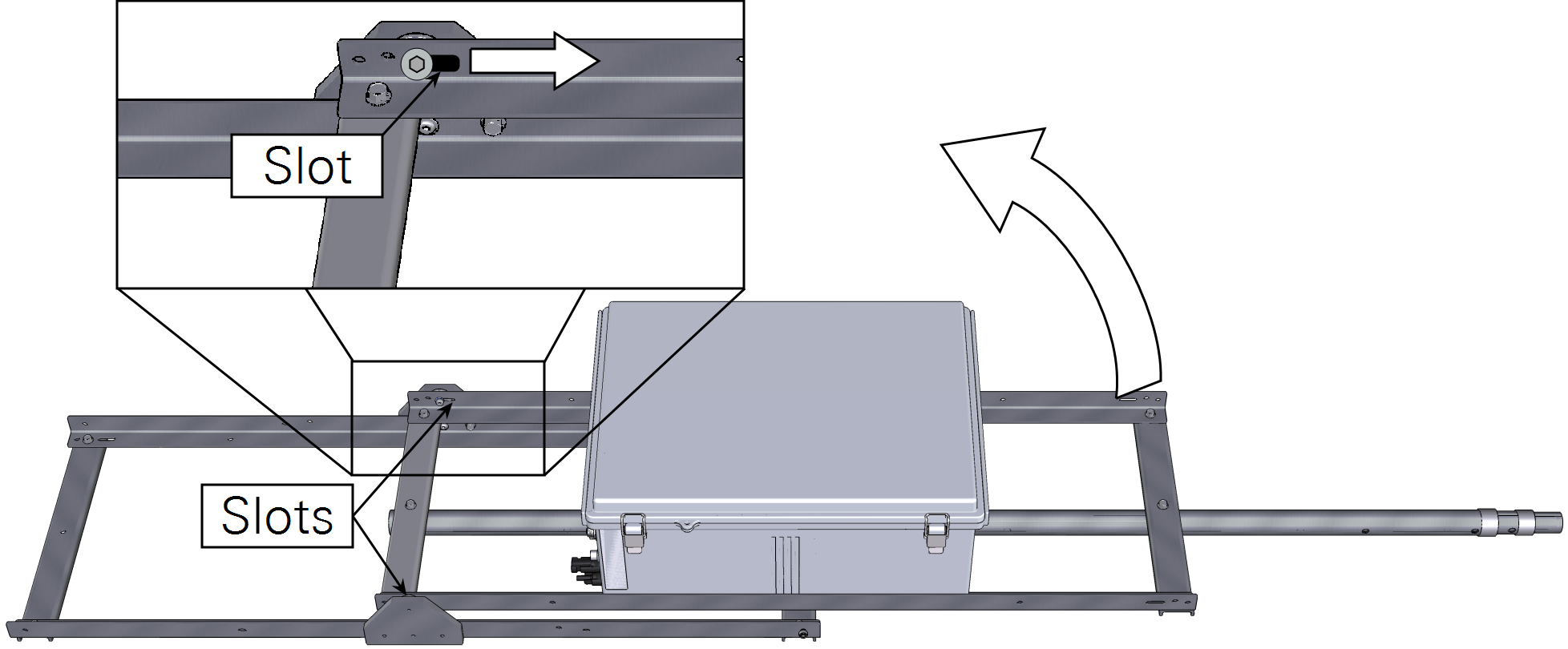
Rotate the enclosure frame to a vertical position.
Be sure the slots are not seated on the pins.
-
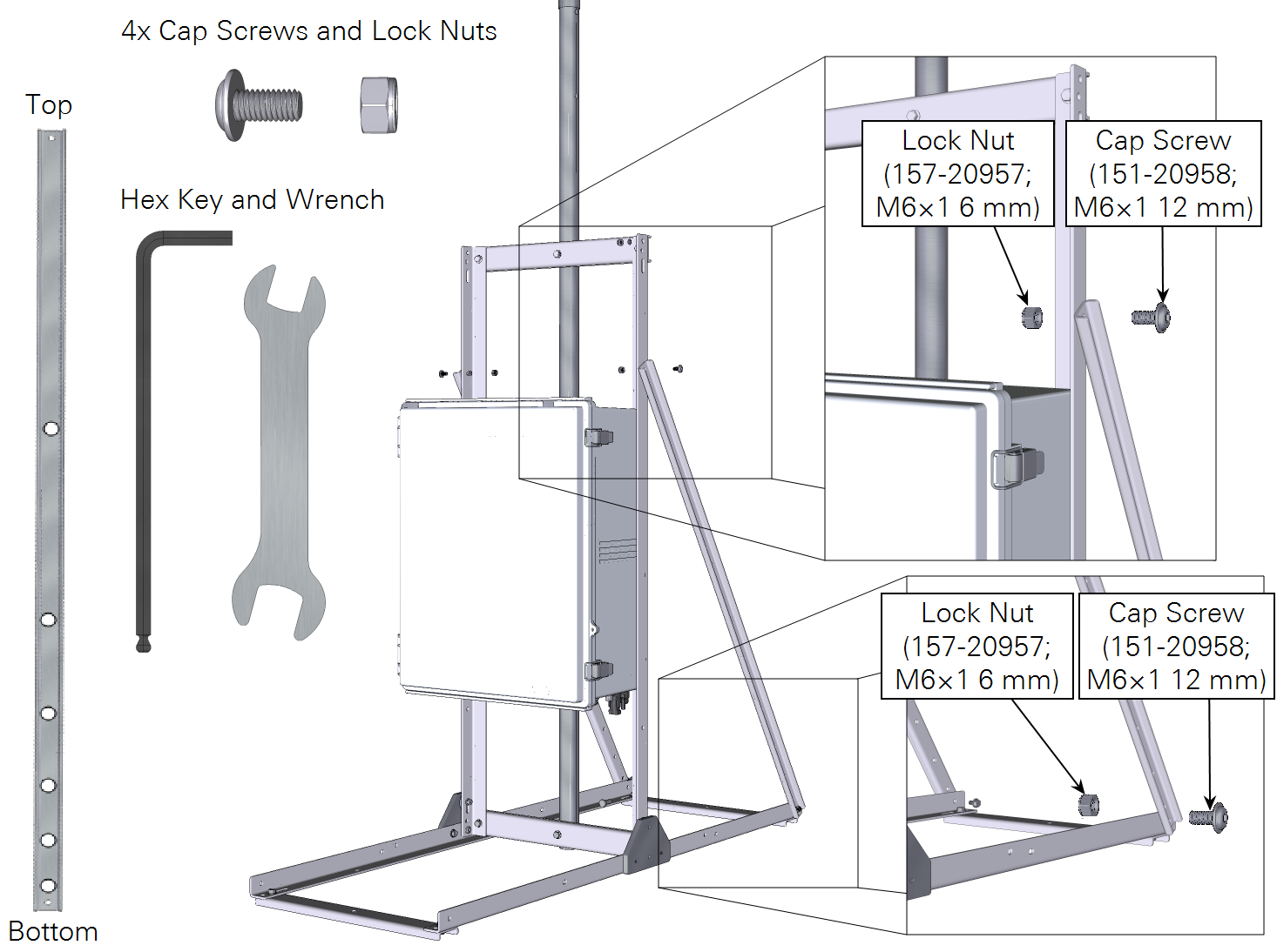
Install two angle-braces to secure the frame in the vertical position.
The high-density panel adjustment holes will be oriented toward the bottom. Install it with four cap screws and four lock nuts.
Installing the battery
Warning: The battery can explode, start a fire, or cause severe burns if the terminals are shorted together. Exercise extreme care when handling the battery. Use insulated tools when practical.
-
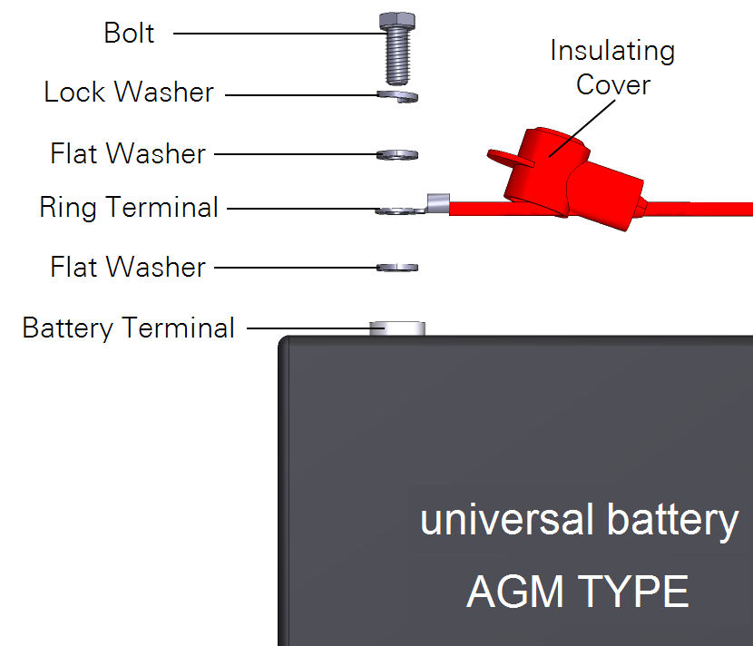
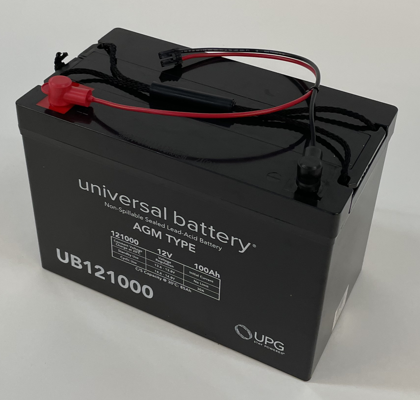
Connect the cable to the battery.
The cable (part number 99512-022) connects to the battery terminal with this hardware arrangement: flat washer, cable ring terminal, flat washer, lock washer, and finally, the bolt. Washers and bolts are included with the battery. Attach the red cable to the red terminal (+) and the black cable to the black terminal (-). Tighten the bolts securely with the wrench and then slide the insulating covers over the terminal.
-
Set the battery on the shelf with the terminals toward the front of the box.
-
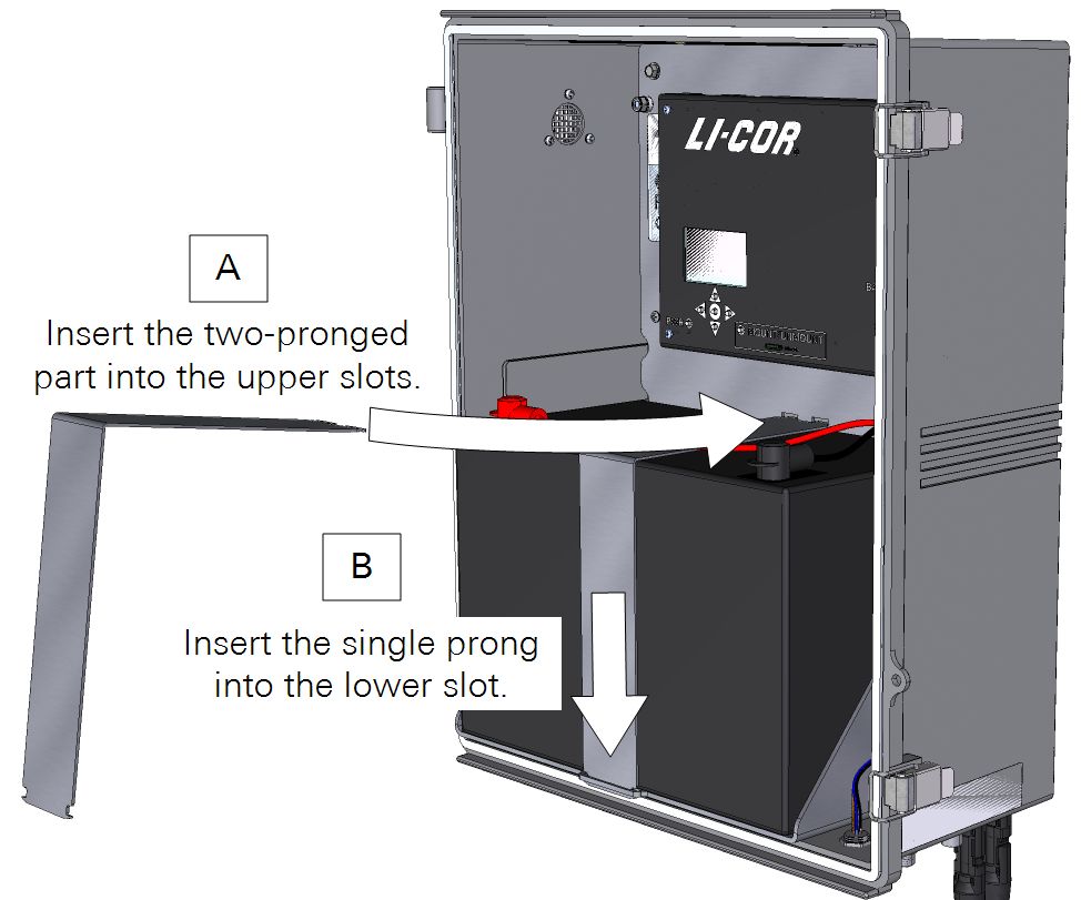
Install the battery bracket.
Insert the two-pronged part into the upper slots (A) and the single prong into the lower slot (B). The bracket holds the battery in place if the system falls over, protecting you and the equipment.
-
Connect the battery cable to the connector.
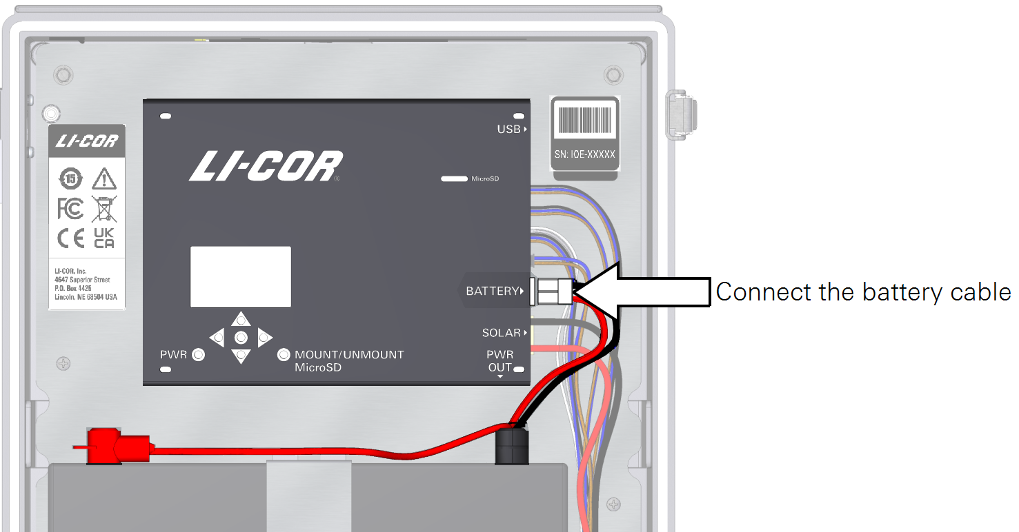
See Removing the main battery for removal instructions.
Using an external power supply
The IoE Module can be powered from an external power supply that delivers 9 to 33 VDC, 3.0 A current. If using an external power supply, do not connect a solar panel or battery. Instead, rely solely on the external power. See Optional auxiliary power cables for cable options.
Field installation
See Initial assembly for the initial hardware assembly.
Site preparation
Place the frame on level ground. The LI-710 can tolerate a tilt of up to 8° from vertical, but installation on level ground with a vertical mast is best. If the ground under the frame is sloped or uneven, use a shovel to level the surface. Pack any soil that was loosened – tamp it with your feet. Position the frame so that the solar panel faces the equator for maximum solar power.
Installing the adapter and LI-710
Caution: Wear gloves and goggles for safety.
-
Insert the two set screws into the adapter until they are flush with the inside wall.
-
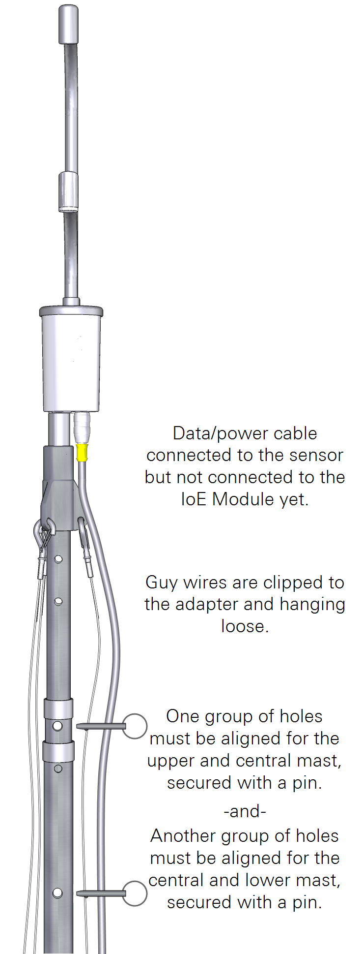
Install the adapter for guy wires and the instrument.
It threads onto the upper mast. Position the mast in such a way that the guy cables are oriented as shown in Figure 2‑1.
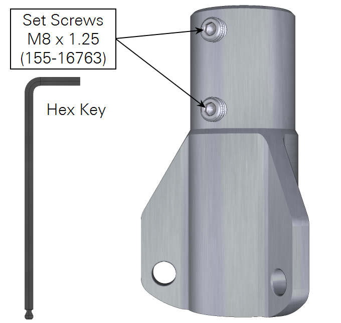
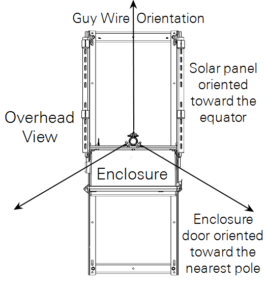
Figure 2‑1. The adapter threads onto the mast. Rotate the mast so one guy wire extends the direction opposite the enclosure door and the other two extend to the sides. -
Connect the power/data cable to the LI-710 and tighten it securely.
Leave the other end disconnected for now.
-
Clip the guy cables in place.
Let them dangle for now.
-
Install the LI-710 in the adapter.
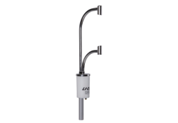
Set the sensor in place and tighten both set screws with the 4-mm hex key. Tighten until it contacts the post, and then an additional ¼ turn clockwise.

Installing the Node Link
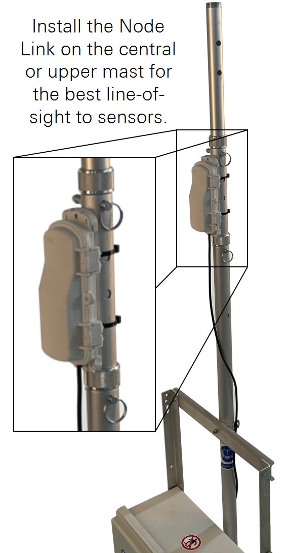
If your Carbon Node includes a Node Link, install it on the central or upper mast segment. Identify the top of the bracket and then attach it to the IoE module mast using two zip ties. Then install the Node Link in the bracket.
See Adding a Node Link to the Water Node for more details on Node Link installation and configuration.
Adjusting the mast
The mast features knurled clasps to hold the sections in position while you make adjustments, and two pins to lock the mast.
Caution: Do not allow the mast to slam down. Use two hands to extend the mast. If the mast de-extends without resistance, instruments attached may be damaged.
For measurement heights between 2 and 3.5 meters, extend the upper section of the mast to the desired height. Tighten the clasp and secure the upper and central portions of the mast with a pin.
For measurement heights between 3.5 and 5 meters, fully extend the upper mast and then extend the central section of the mast to the desired height. Tighten the clasp and secure the lower and central sections of the mast with a pin. The mast can be adjusted in 20 cm increments. Both pins are needed to secure the mast when it is extended. One pin secures the central and upper mast sections; the other pin secures the central and lower mast section.
Installing earth anchors and guy wires
Guy wires are required for stability if the mast is extended. If the mast is not extended, sandbags can be used to stabilize the platform.
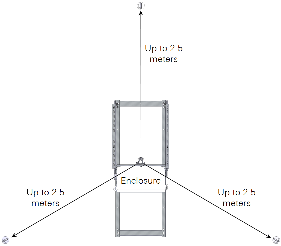
If you stand facing the door of the enclosure, one guy wire should be oriented directly away from you, one should be to your right, and the other to your left. Rotate the mast until the fins on the adapter are oriented that way.
The guy cables should be around 20° to 30° angle from the mast. You can approximate the angle by pacing off the distance or measure the angle with an app on a smart phone.
-
In the direction that each guy will extend, pace off or measure the distances for the anchors.
-
Mark points for the three earth anchors on a radius around the mast, providing three equidistant anchor points along the radius.
-
Drive the earth anchors straight into the ground, perpendicular to the surface.
To install, insert the ground rod through the eye bolt. Use the rod as a lever to drive the anchor, being careful to avoid bending the rod. Or, use an impact wrench and a 1 3/8" socket.
-
Drive each anchor until all of the threads are below the soil surface.
If the opening in the eye bolt is not perpendicular to the mast, drive it further until the opening is perpendicular toward the mast.
-
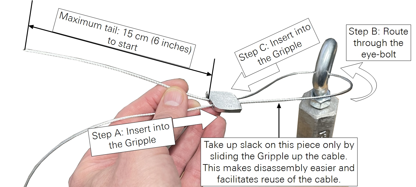
Install the guy cables.
-
Tighten each guy wire to achieve equal tension.
Guy wires should not apply any load to the mast. They should be just tight enough to provide stability.
Releasing a Gripple (loosening a cable)
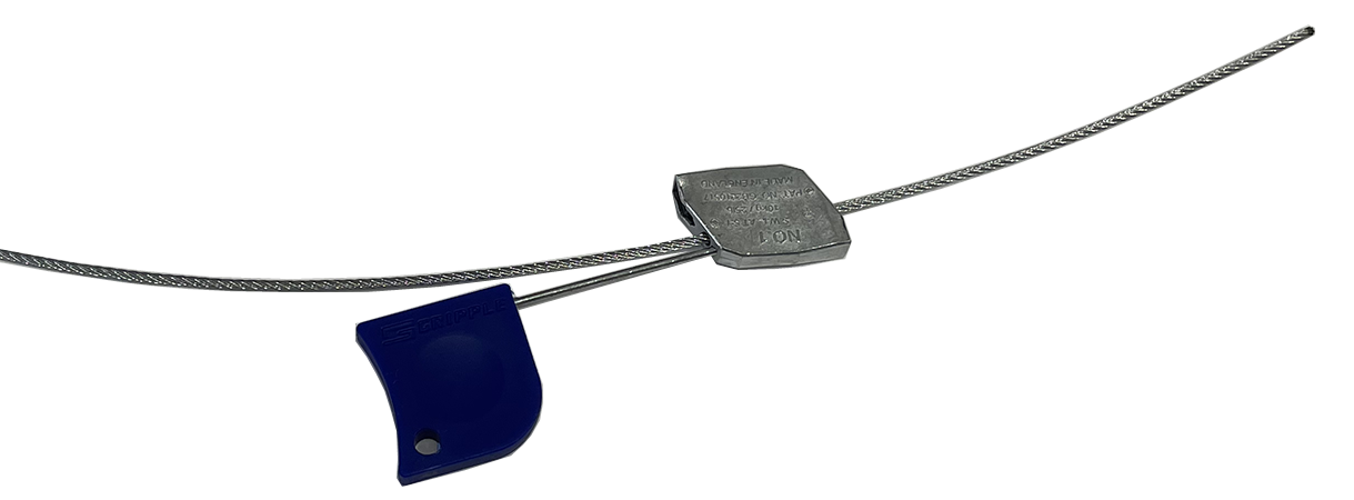
Gripple cable locks can be released with the key (part number 611-21003). Insert the key in the hole adjacent to the cable. Press the release key until the cable moves freely in the Gripple. If the Gripple has been in the field for a while, dirt or corrosion may make it difficult to release. First, attempt to tighten the cable slightly to loosen the mechanism. If you are unable to free the cable, you may need to cut it. Make the cut in such a way that you preserve a long, usable piece of cable.
Installing the ground rod
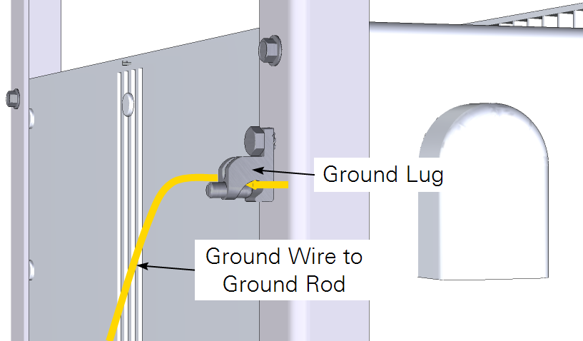
The ground kit includes a ground rod, copper wire, and clasp. The ground rod can be inserted into the ground to ground the equipment. Drive the ground rod as close as possible to the IoE Module frame, preferably between the lower rails, behind the enclosure to prevent tripping hazards.
To drive the ground rod, use a hammer drill with ground rod bit or a sledge hammer. Attach the copper wire between the ground lug on the back of the box and the ground rod using the ground wire clamp. Tighten it with the 1/2" open-end wrench and slotted screwdriver.
Attaching the solar power supply
If your system has solar power components, attach them as described here. Install the battery as described in Installing the battery.
-
Consider the ideal angle for the solar panel.
Determine the ideal attachment point for the lower U-rails to position the solar panel at an angle that faces the sun at midday. The angle of the panel can be the same as the latitude of your site to ensure optimal charging. For example, installations in northern Canada, Sweden, or Siberia will have optimal charging with the panel at a 45° angle and a southward orientation.
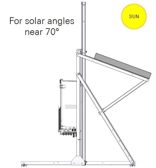
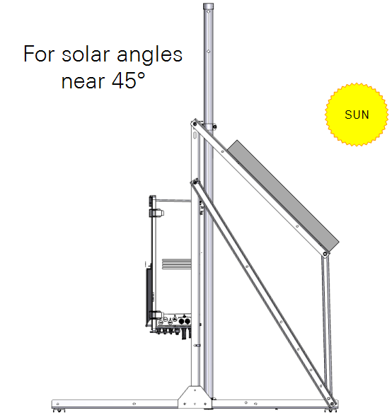
Figure 2‑3. Orient the panel so it has the maximum exposure to sunlight. -
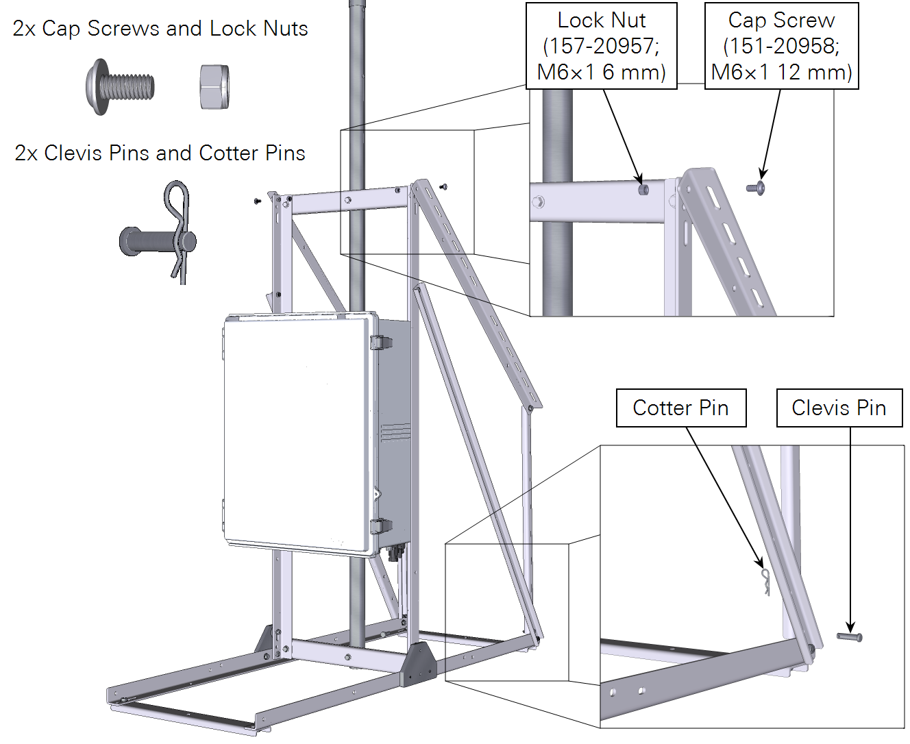
Attach the solar panel rails at the desired angle.
The upper angle rails attach to the top with two cap screws and nuts. The lower U-rails attach with two clevis/cotter pins.
-
Remove the panel from the box and discard the packaging material.
Retain the warranty information and manufacturer's documentation.
-
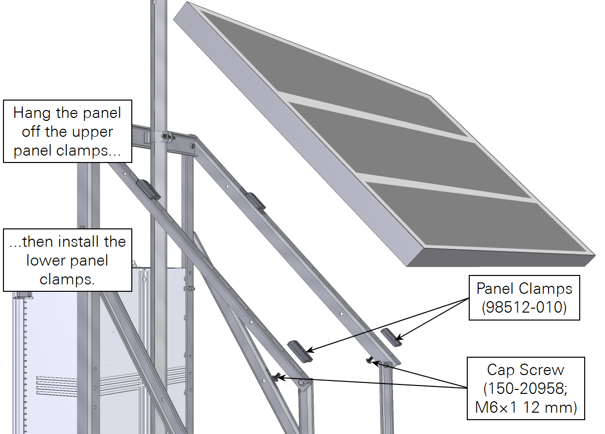
On the panel frame rails, loosely install two upper clamps as shown.
-
Place the solar panel over the upper clamps so they hold the frame to the rails.
-
Install the two lower clamps under the solar panel frame.
You may need to adjust the position of the panel and clamps to ensure that all four clamps secure the panel frame.
-
Tighten all four clamps securely.
-
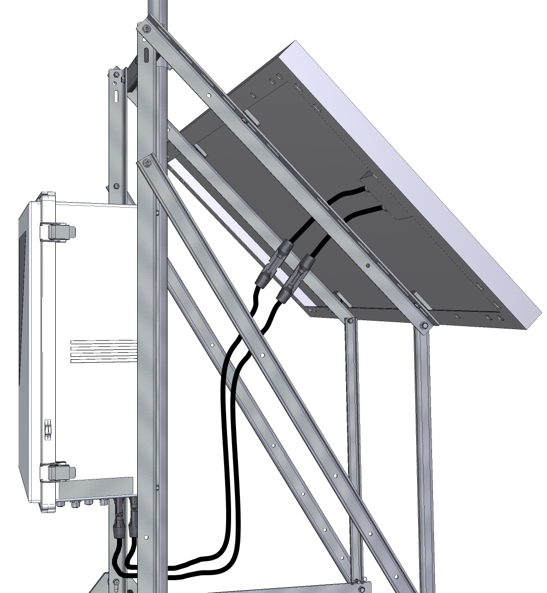
Install the solar panel power cables between the panel and the two connectors on the bottom of the enclosure.
