
Making Measurements
The presentation in this chapter presumes that you have assembled the LI-6400, learned how to operate the software - especially the chamber control functions - and are ready to make measurements on plants.
Preparation Check Lists
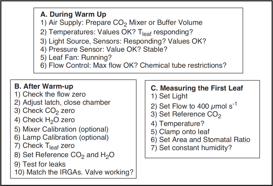
We present a checklist of things that should be done prior to making measurements. They take about 5 minutes, but if you are careful to do this each session, it can save you a lot of time and frustration later. You may wish to copy and clip this checklist summary:
During Warm Up
Once OPEN is loaded, and while the gas analyzers are warming up, you should do these steps.
- Air Supply - Cartridge or Buffer Volume?
- If you are going to be using the 6400-01 CO2 mixer, install a cartridge now, so the system can begin pressurizing. Otherwise, prepare a buffer volume (see Air Supply Considerations).
- Check the Temperatures
- The three measured temperatures (block, air, and leaf) are together in display group h. Check to see that they read reasonable values, and are within a few degrees of each other.
- Position the thermocouple properly, either just above the gasket (Figure 19‑23) for leaf measurement (normal), or pulled down for air temperature measurement (energy balance).
- Check the Light Source and Sensors
- Check to make sure that the instrument is configured for the light source that you are using. See Specifying the Source and Sensor on page 8-3 in the instruction manual.
- The light sensors (ParIn_μm and ParOut_μm) are both in default display group g. See that they respond as expected when the light sensors are illuminated and darkened.
- If you get negative ParIn_μm values, there is probably a mismatch between the real light source, and the one OPEN thinks it has. A trip to
<open> <light><source>in Config Menu|View/edit will fix that. - Check the Pressure Sensor
- The pressure measurement (Prss_kPa) is shown in display group g. See that it shows reasonable, stable values. (Typical values: 100 kPa near sea level, 97 kPa at 1000 ft., 83 kPa at 5000 ft., etc., but this varies with the weather.)
- Check the Leaf Fan
- Turn the leaf fan off and on (f3 level 3), and listen for sound changes in the sensor head as the fan motor stops and starts. If you do not hear a sound when the fan should be on, it could mean a blown fuse (fan or flow board), a fan jammed with debris, or other problems (see Troubleshooting). Leave the fan on when you are done.
- Is Flow Control OK?
- Use the flow control key (f2 level 2) to fix the flow at 1000 μmol s-1. Watch the Flow_μms (display group b) to determine the actual maximum flow. The value is typically in the 700’s if a CO2 mixer is installed, or higher if not.
- Now test the chemical tubes for flow restrictions by changing each from full bypass to full scrub, and watching the effect on flow rate. Normally, scrubbing will drop the maximum flow by 5 or 10 μmol s-1 per tube. Larger drops may indicate that the air mufflers in the chemical tubes are getting clogged, or that a flow diversion tube is pinched shut. See Pump/Flow Problems for more details.
- Finally, set the flow to 500 μmol s-1.
After Warm Up
After the IRGAs have been on for about 10 minutes1, continue with the following steps:
- Check the Flow zero
- In New Measurements mode, monitor Flow_μms (display line b) and turn the pump off (2 f2 N) and the chamber fan off (3 f3 O for off)2. The flow should drop to within 1 or 2 μmol s-1 of zero. If it doesn’t, re-zero the flow meter (Zeroing the Flow meter). Turn the fan back on when done.
- Adjust the latch, and close the chamber
- 1) Adjust the latch so that the chamber lips are slightly apart when the chamber is closed. 2) With the chamber closed, close the adjustment knob until it starts to become snug. 3) Open the chamber, and turn the knob one or two more half turns. Now the chamber is adjusted properly for sealing when empty, or with thin leaves. Close the chamber for the next two steps.
- Check the CO2 IRGA zero
- In New Measurements mode, with the mixer off (2 f3 N), and the flow set to 500 μmol s-1 (f2 F 500 enter), monitor CO2 reference and sample (display line a). Turn the soda lime on full scrub, and the desiccant on full bypass. The reference should quickly approach zero, while the sample will approach zero a bit more slowly. If they are within 5 μmol mol-1 of zero, it will be adequate.
- Check the H2O IRGA zero
- Turn the desiccant to full scrub, and watch sample and reference H2O. The reference will again approach zero faster than the sample does. It will zero more slowly than the CO2 IRGA did, however, because of water sorption.
- Rather than wait the 10 or 20 minutes to get a really good zero, use your judgment. If after a minute or so, the reference is down to 0.2 or 0.3 mmol mol-1 and falling slowly, that’s good enough. The sample will be higher than that. Clearly, if it’s negative and falling after only 1 minute, it will be going too low, and re-zeroing may be in order.
- If the CO2 or H2O IRGAs need zeroing, refer to Setting the CO2 and H2O Zero. The important thing is that the reference IRGAs are reasonably well zeroed (let’s say ±5 μmol mol-1 CO2, ±0.5 mmol mol-1 H2O). The first time you match (Step 10, coming up), the sample IRGAs will be taken care of, as they are adjusted to match the reference IRGAs.
-
Important Note about CO2 and H2O Zeros:
If your chemicals are not fresh, then you will do more harm than good by setting the zeros with them.
The IRGA zeros are quite stable, especially in the absence of big temperature changes. Therefore, the exercise of checking zeros each day is really a diagnostic. If the indicated concentration doesn’t change when it should (that is, if it doesn’t drop when you start scrubbing), then something is wrong, and it’s good to find that out early.
- Mixer Calibration
- If you are using the 6400-01 CO2 Mixer, run the routine found in Calib Menu|CO2 Mixer|Calibrate, described in Calibrating the CO2 Mixer. The chamber can be open for this. Make sure that the soda lime is on full scrub.
- Lamp Calibration
- If you are using the 6400-02 or -02B LED Source, or the 6400-40 LCF, run its calibration (
Calib Menu|LED Source|Calibrate, orCalib Menu|LCF Source|Calibrate; see Calibrate...). You will do the best calibration by having the chamber closed onto a representative (with respect to its reflectance) leaf. This isn’t critical however, but the chamber should at least be closed. - Check Tleaf zero
- Unplug the leaf temperature thermocouple connector (it’s purple colored), and compare the leaf and block temperatures. If they differ by more than 0.1°, then adjust the leaf temperature zero (see Zeroing the Leaf Temperature Thermocouple).
- Finally, reconnect the thermocouple, open the chamber, and verify that “Tleaf_°C” responds when the thermocouple is warmed by touching it.
- Set Desired Reference Values for CO2 and H2O
- If you are using the CO2 mixer, set it to control on reference concentration with a target of 400 μmol mol-1. Make sure that the soda lime is on full scrub. If you are not using the CO2 mixer, monitor the reference CO2 concentration. Is CO2R_uml sufficiently stable? (Over a 30 s period, it should change less than 2 μmol mol-1.) If not, use a larger buffer volume.
- For H2O, set the desiccant at mid-range (between scrub and bypass) for now.
- Leaks?
- Set the flow rate to 200 μmol s-1. With the chamber closed and empty, exhale around the chamber gaskets, and look for any fluctuations in the sample cell CO2 concentration (CO2S_μml, display group a). If there are no leaks, the CO2S_μml value should not increase by more than 1 μmol mol-1.
- Match the IRGAs
- Matching the IRGAs is easily accomplished whether the chamber is empty or not, but it’s a good policy to do this once right before starting a measurement. Refer to Matching the Analyzers for how to do this.
Verify that the match valve is in fact working. Figure 4‑2 shows what to look for.
You are now ready to clamp onto a leaf and begin measurements.
Clamping Onto the First Leaf
Once you’ve got the system behaving well with no leaf in the chamber, you are ready to start. The basic procedure is quite simple: set the conditions in the chamber, insert the leaf, adjust the conditions if necessary, then wait for stability.
- Light
- If using the LED source, set the light to the desired value (ambient is a good value to start with - it won’t be an abrupt change for the leaf). If you aren’t using the LED source, then orient the chamber so that no shading of the leaf by the chamber walls will occur once you’ve installed the leaf.
- Flow
- Set the control for Fixed flow, about 400 μmol s-1, and desiccant mid-range between scrub and bypass. We’ll come back to this in Step 9.
- CO2
- If you are using the CO2 mixer, set it to control reference CO2 with a target slightly above ambient (say, 400 μmol mol-1). If you aren’t using the CO2 mixer, but using a buffer volume instead, set the soda lime scrub knob to give you the concentration you want. Usually, that means full bypass.
- Temperature
- (Optional) If you are going to be in direct sun, you will probably want to use the coolers to control the temperature. Check the temperatures to see their present values, then set the control accordingly.
- Insert leaf
- Check the latch adjustment for a good seal. Snug is fine; be careful it’s not too tight, however. If you aren’t using the LED source, be careful with the chamber’s orientation; avoid shading part of the leaf with the walls of the chamber.
- Set Stability (optional)
- Use Define_Stablty (f4 level 5) to setup the stability criteria you wish to use (Defining Stability on page 6-29 in the instruction manual).
- Log Options, Log Button (optional)
- This is a good time to set your log options (Log Options, f3 level 5) and your log button behavior (f5 level 5), if you wish. See User Definable Log Button on page 9-7 and Log Options on page 9-15 in the instruction manual.
- Set Area and Stomatal Ratio
- In New Measurements mode, press 3, and set the leaf area and stomatal ratio for this leaf. Leaf area is simply the area exposed inside the chamber. If you are using a 2x3 chamber and filling it, the area is 6 cm2. Stomatal ratio is an estimate of the ratio of stomata on one side of the leaf to the other. Use 1 for equal stomatal density on top and bottom; 0 for stomata on only one side. If you aren’t sure, use 0.5. It doesn’t matter if you use the ratio of top to bottom, or bottom to top. Thus, 0.5 is the same as 2; 0.333 is the same as 3, etc.
- Revisit the flow control
- Decide how you will operate: control flow to maintain constant humidity, or use a constant flow. (If you aren’t sure what to do here, you probably skipped over Tour #3: Controlling Chamber Conditions. There may still be hope for you, however; work through Humidity Control Experiments.)
From this point on, what you do is going to depend on your experiment, or what it is you wish to accomplish. For example, you might wish to measure a response curve (light, for example, is discussed in Light Response Curves), or make survey measurements (see Making Survey Measurements) by going from leaf to leaf and only taking a minute or so for each measurement.
If you are new to gas exchange measurements on plants, continue on with the next section (Some Simple Experiments). It will take you through some principles that should help you make valid measurements.